Wiring harness routing & packaging Rules Week 3 Challenge
1 A) CLAMP
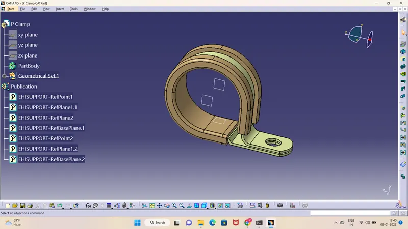
1) Download the required part file from the te.com
2) In the part design create points and planes at the entry, exit and base.
3) Switch to Electrical part design, Select the DEFINE SUPPORT PART
4) Give the entry point and plane as first plane, exit as second plane and base as third plane.
5) Repeat the step 3 and 4, this time give opposite end as entry.
6) Clamp electrical properties are assigned.
2 A) BACK SHELL
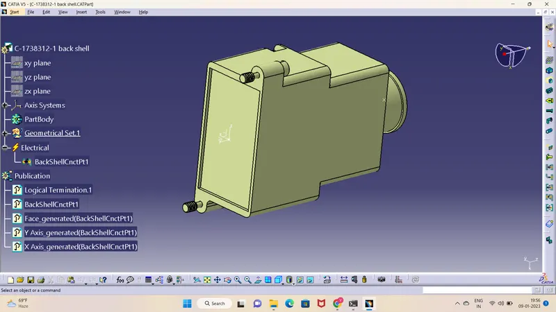
1) Download the back shell from te.com
2) Create point and axis at the bundle entry point (where connector comes into contact).
Y-axis: In the direction of bundle
X and Z – any direction.
3) Switch to Electrical part design. Click on DEFINE BACKSHELL. Select the part body, keep the type as uncut.
4) Now click on DEFINE BACKSHELL CONNECTION POINT. Give the representation as centre point, Coincidence as Y-axis and Orientation as X/Z axis.
5) Electrical properties to back shell are assigned.
3 A) COT TUBES
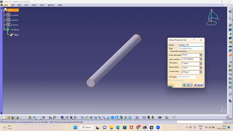
1) Create a new part in electrical part design.
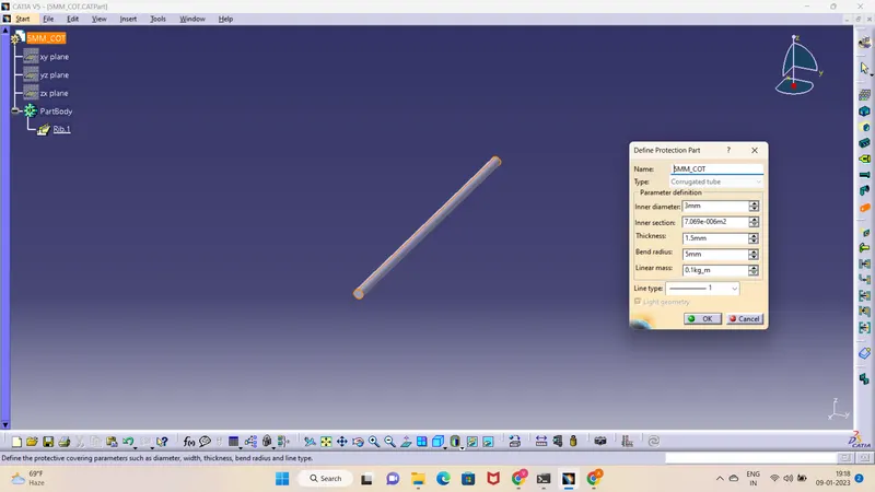
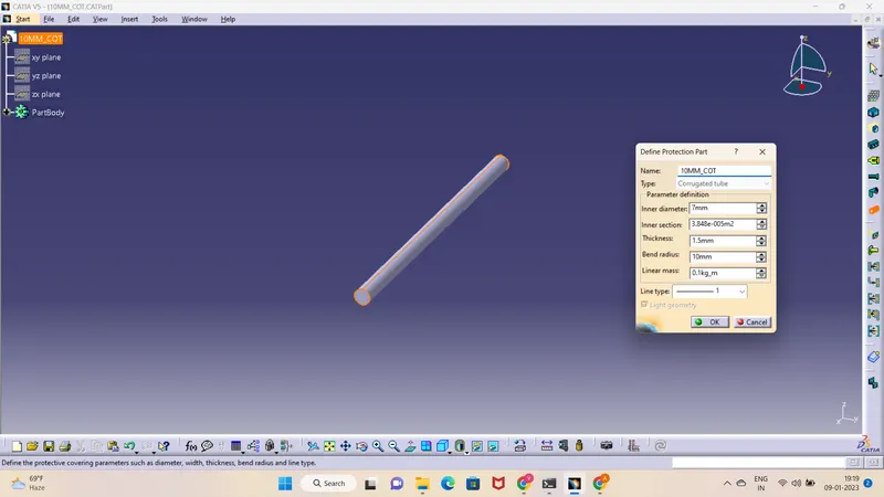
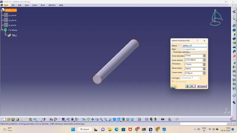
2) Select DEFINE PROTECTION PART
3) select the axis system.
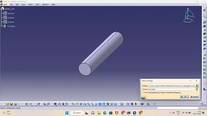
4) Give the inner diameter, outer diameter and save the cot tube in separate catalogue created for corrugated tubes and insulation tapes.
5) Repeat the same steps for creating all corrugated tubes
CONCLUSION
The required clips, backshells, corrugated tubes, and insulation tapes are defined electrically in CATIA V5 and are stored in the respective catalogs.