Wiring harness routing & packaging Rules Week 3 Challenge
Wiring harness assembly structure – CLIP DEFINITION
The Clips are one of the important parts in automobile electrical harness assembly. The Clips are used to fix the electrical bundle at certain position on another part, to avoid its contact with neighbor parts.
The clips also help in preventing the electrical bundle to get tangled with its neighbor electrical bundle, when set free.
The Clips are available in various shapes and sizes based on the requirement and its usage.
The Various types of clips available are shown below,
- P-CLIP
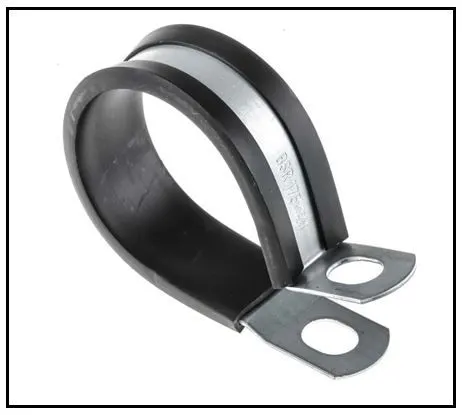
The above P-CLIP can be of ferrous/Non-ferrous material based on the requirement and usage.
The above P-CLIP is a metallic material with an insert. Usually, the insert may be of rubber/thermoplastic/thermoset material.
- FIR TREE MOUNT TUBE CLIP
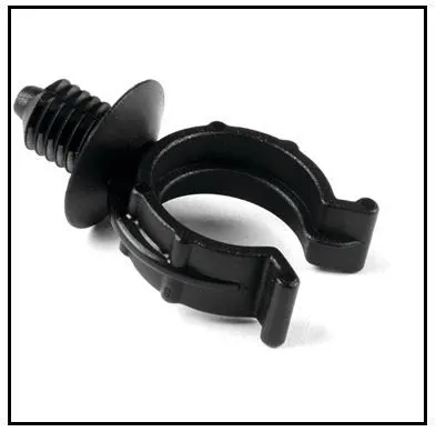
The above Fir tree mount tube clip designed to offer a durable single-hole mounting, as this tube clip allows the installer to insert the fir tree with minimal force while providing a secure hold. The above fir mount tube clip is made up of Polyamide 6.6 high impact modified, heat and UV stabilized material, with an operating temperature of -40°F to +221°F (-40°C to +105°C).
- STICK CLIP
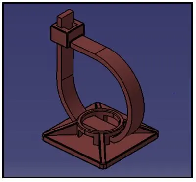
The Stick Clip functioning is similar to “tie wrap”. The Stick clip surrounds multiple electrical bundles firmly by the action of tightening pull applied at the free end of the clip.
The Stick clip comes with a base as a special requirement, for mounting purpose.
- Defining of P-CLIP as an electrical support using electrical part design workbench in CATIA V5
The following important parameters required to define clip is shown below,
- Entry Point and Plane.
- Base Plane.
- Exit Plane.
The Flow chart for defining the clip as an electrical part is shown below,
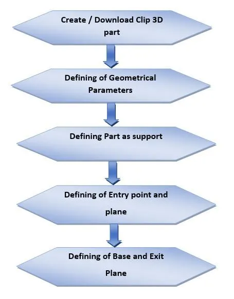
The Clip used for defining as an electrical support is P-CLAMP/P-CLIP.
The clip 3D part is downloaded, followed by which the necessary points are defined on the clip and the part is defined as a support.
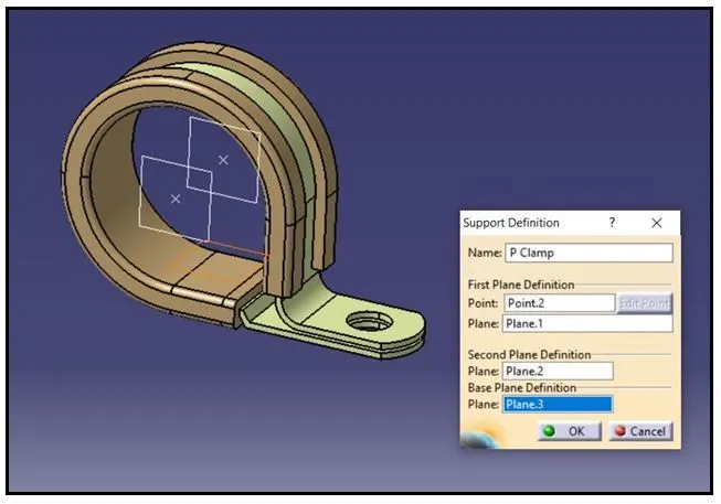
The Entry point and entry plane are defined, by using the point definition and plane definition command.
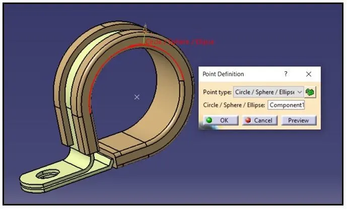
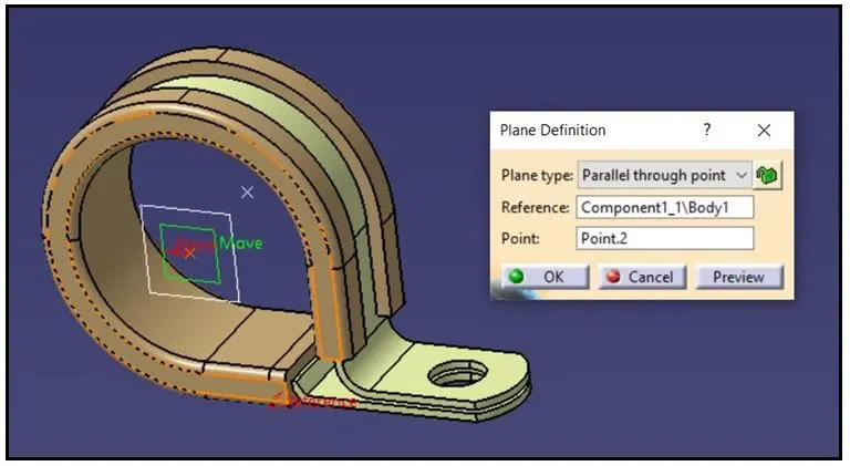
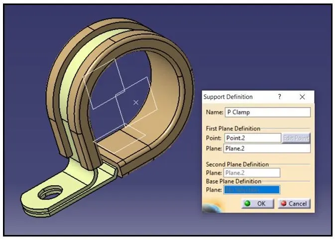
Once the entry point and entry plane are defined, then the exit point and exit plane should be defined for the bundle exit.
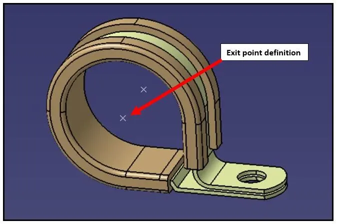
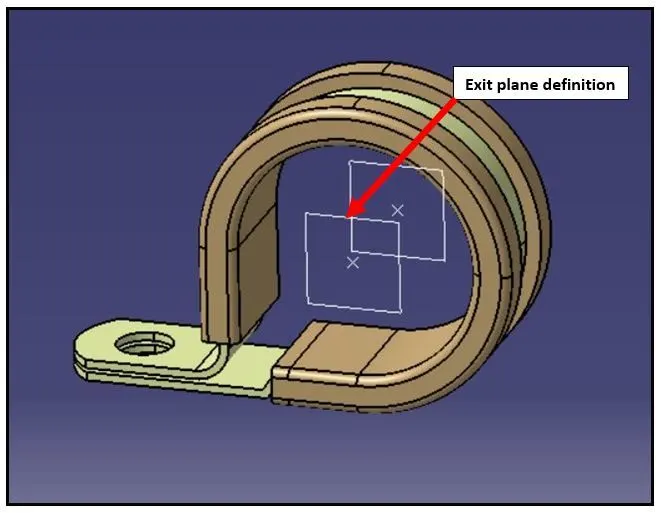
After the exit point and exit plane are defined, then the third plane should be defined, which is the base plane. The base plane is for the bundle to rest inside the clip base.
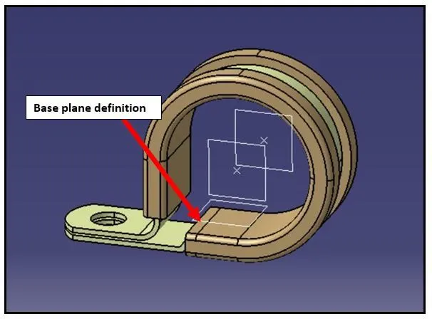
After all the points and planes are defined, finally the part is to be defined as a support in CATIA interface to be used in the next stage of wiring harness design.
The Support definition for entry point and entry plane is shown below,
The Support definition for exit point and exit plane is shown below,
- Defining of BACKSHELL as an electrical part using electrical part design workbench in CATIA V5\
The following important parameters required to define the backshell as a electrical part is shown below,
- Defining of Backshell connection point.
- Defining of Bundle connection point on Backshell.
The Flow chart for defining the Backshell as an electrical part is shown below,
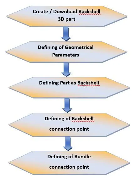
The desired backshell as per the requirement is created or the 3D part file is downloaded from the online sites.
After creating/downloading the 3D part, the geometrical parameters are defined on it.
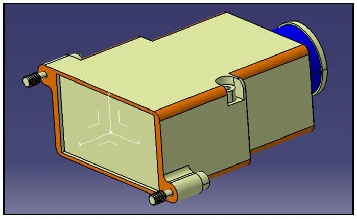
The geometrical parameters to be defined on the part are shown below,
- Point definition.
- Axis system definition.
The point and axis system definition in the Backshell 3D part is shown below,
Once the point and axis system is defined, the backshell 3D part is defined in CATIA using backshell definition command as shown below,
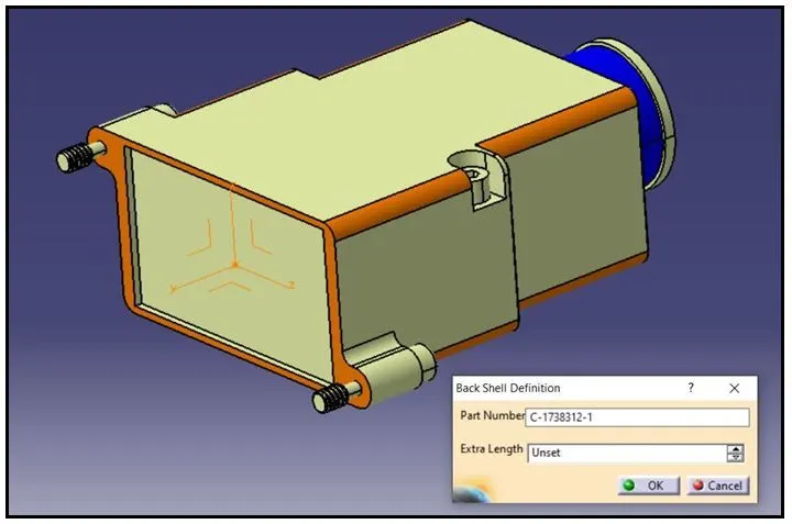
The backshell connection point is defined which can be performed, only when the backshell is defined using “Backshell definition” command.
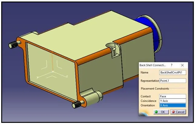
The backshell connection definition enables to mate the backshell to the connector in electrical assembly workbench, only when the point and axis system is defined in connector.
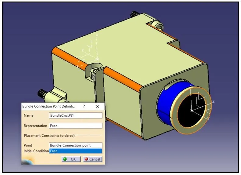
Once the backshell connection point is defined, the bundle connection point is to be defined for the entry of bundle inside the backshell.
In the bundle entry of the backshell, there should be point and axis system to be defined.
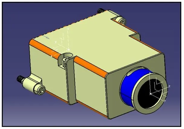
After the point and axis system is defined, the bundle connection point is to be defined using “bundle connection point definition”
- Creation of CORRUGATED COT TUBES and adding them in CATALOG named under “slit-COT” family.
The CORRUGATED COT TUBES are created in electrical part design workbench using “Define protection part” command.
The define protection part command has a set of input data, which has to be entered in order to create the desired COT TUBE.
The main input data to be entered for crating the COT TUBE is shown below,
- Internal Diameter in MM of the COT TUBE.
- Thickness of corrugated tube in MM.
- Bend Radius in MM.
The various sizes of CORRUGATED COT TUBES created in electrical part design workbench is shown below,
- 5mm COT TUBE
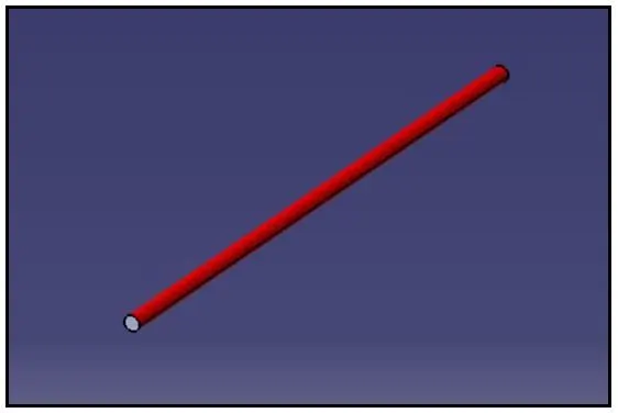
- 10mm COT TUBE
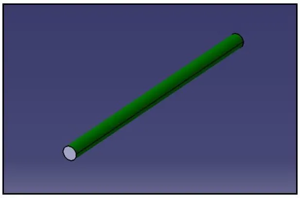
- 15mm COT TUBE
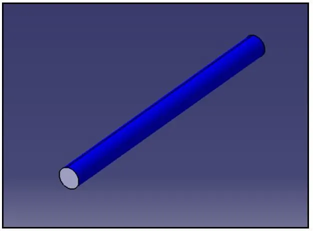
- 20mm COT TUBE
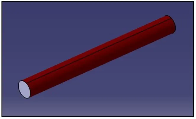
- 35mm COT TUBE
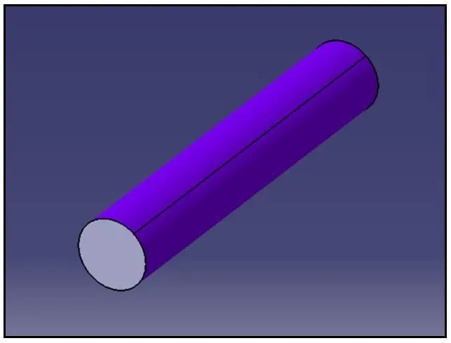
Once all the COT TUBES of desired sizes are created, then the COT TUBES can be added to a specific catalog for future use.
The CATALOG is created in a new document using the “CATALOG DOCUMENT” command in CATIA.
In the catalog document, firstly we have to select the ‘ADD FAMILY” option for defining the family for CATALOG.
The name for the CATALOG is to be provided followed by selection of category type for which the CATALOG is created.
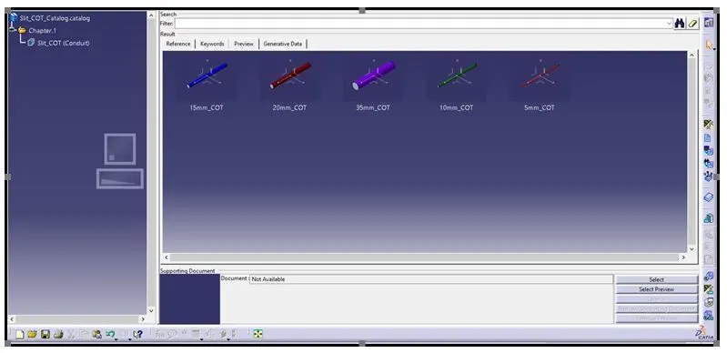
Here, we are making CATALOG for storing the different sizes of corrugated cot tubes as created shown in above images.
The CATALOG for the corrugated cot tubes is shown below,