Wiring harness routing & packaging Rules Week 3 Challenge
1)
Aim:- To define the given part as electrical support using electrical part design workbench.
process:
Download the 3d clip and convert the given into solid
Define the geometrical parameters
- create entry point and exit point
- create two planes with refrence to those points and also the base plane with reference to the base.
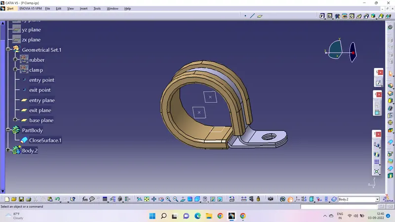
- Switch to electric part design
- click support defination and select the part - select entry point and entry plane - select exit plane - select base plane.
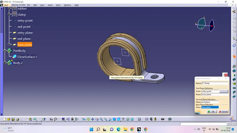
- Again repeat process and select one point and plane - select base plane - another plane will be selected by default
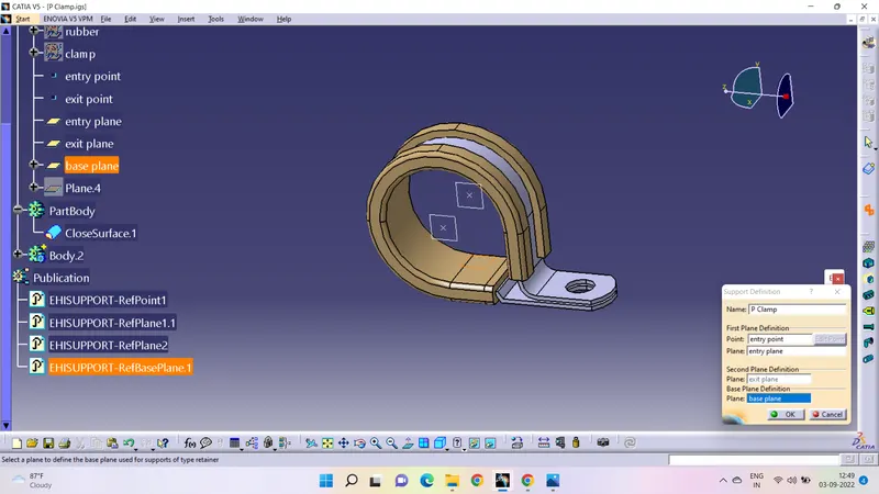
2 ans:
Aim is to define the given 3d model as back shell using electric part design workbench
Process:
- open the given 3d model in the part body and create back shell entry point and axis with reference to that point for back shell entry.
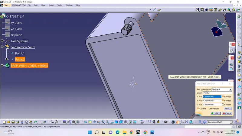
- create bundle connection point
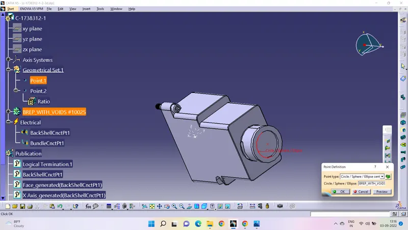
- Switch to electrical part design and define part electrically as back shell.
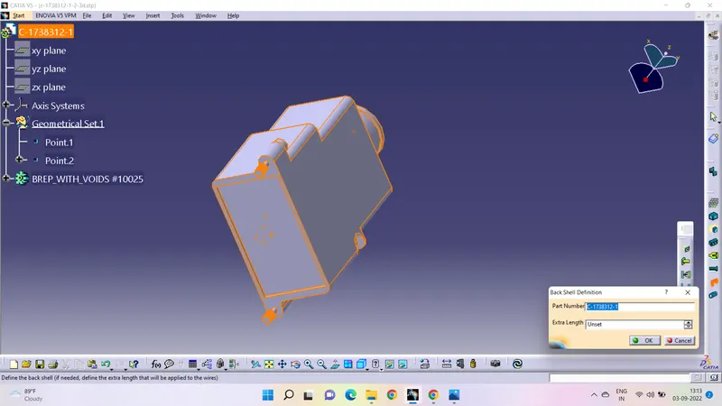
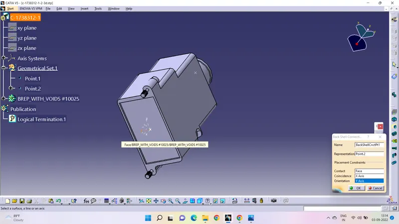
- Then define back shell connection point.
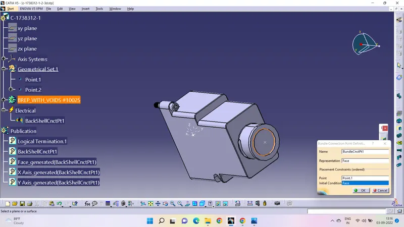
- Define bundle connection point with reference to the point created.
3ans:
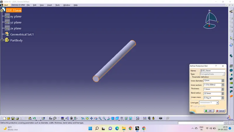
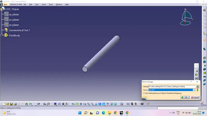
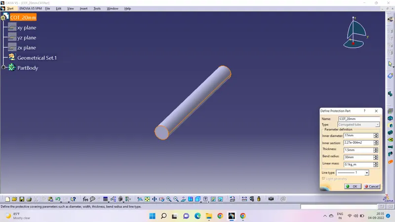
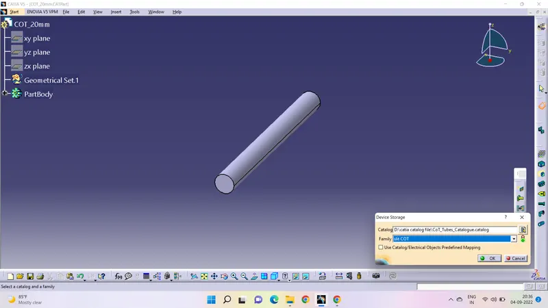
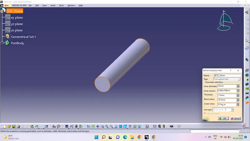
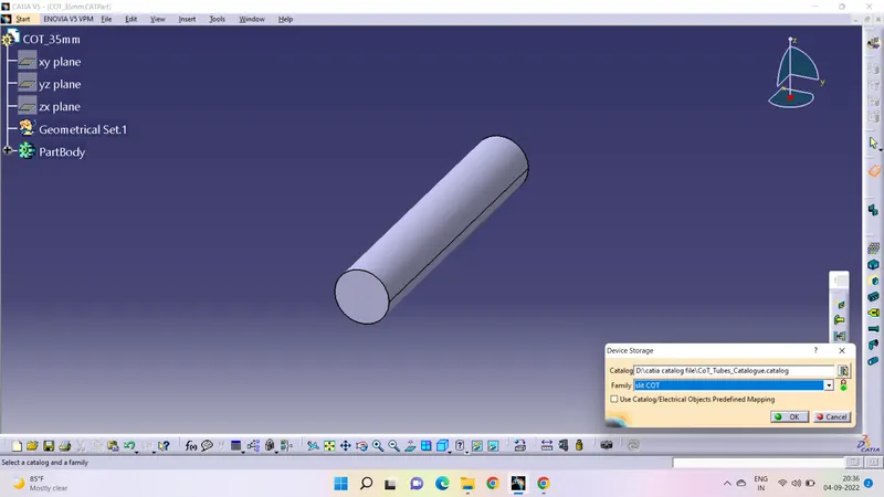
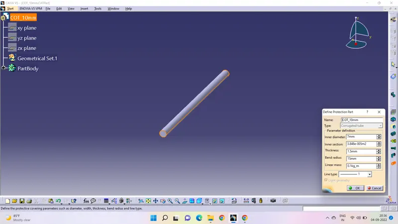
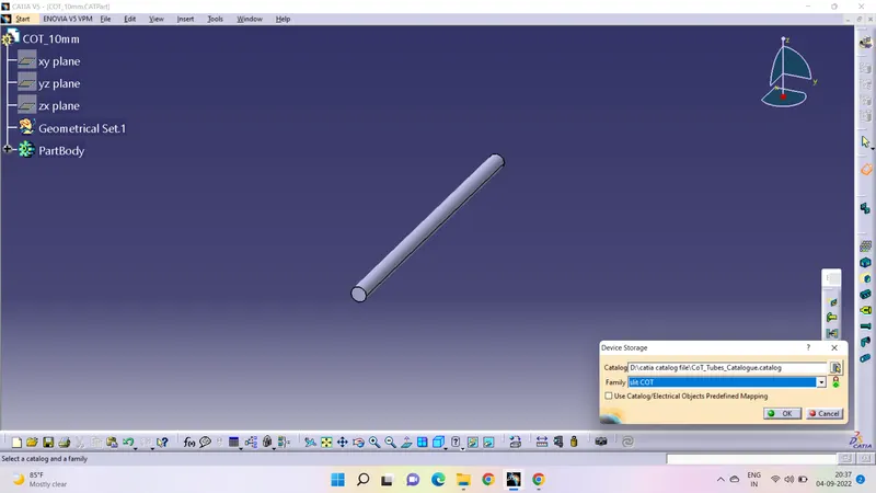
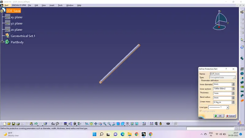
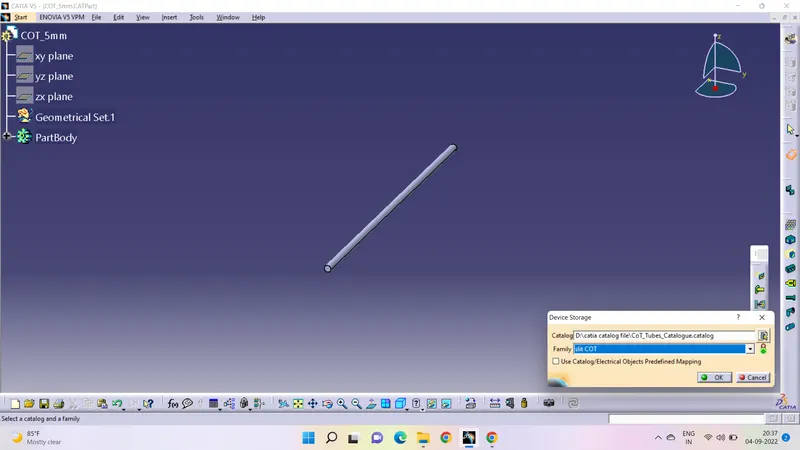
Aim is to create 3D Cot tubes as per given parameters and to be added them in catalogue under "slit COT" family
PROCESS:
- Open electric part design
- Select the define protection part
- Select the part body from the tree structure
- Enter the name and give the required parameters
- the bend radius must be 1.5 x OD given
Catalogue Creation:
Slect new - catalogue document- Add family- give family name as mentioned in the question ("slit COT") - Save
Add each component created to the slit Cot family individually in the catalogue created.
Images for clear reference: