Wiring harness routing & packaging Rules Week 3 Challenge
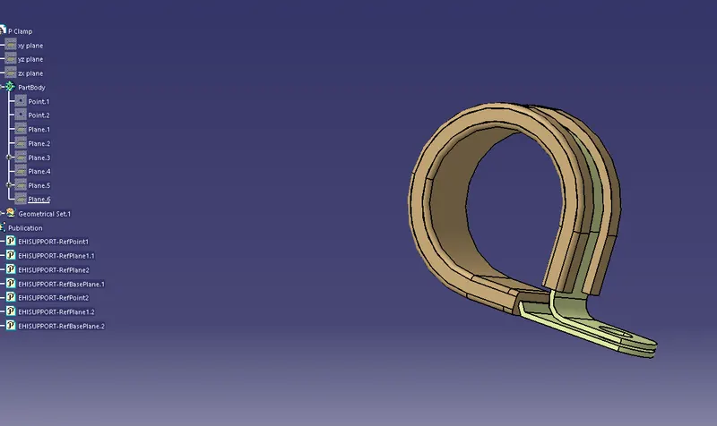
Q1. P Clamp
-Open the P Clamb part in part design
-Create points on both side of clamp.By clicking point in the reference element toolbar.
-Select the point type as circle/sphere/ellipse center.
-click on the circumference of the circle to create a point in the center.
-Create a plane on the side of clamp.By selecting the surface and point

-Create another plane offsetting from a distance 2mm from the base on rubber.
-Switch to electrical part design by clicking the workbench toolbar.
-Define P Clamb as a Support in clicking on Support definition in electrical device definition toolbar.
-Select the first plane and point,second plane and base plane.
-Again define the support , taking the second plane and point( if unable to select point ,reset the point selection)and the base plane.
Q2 Back shell
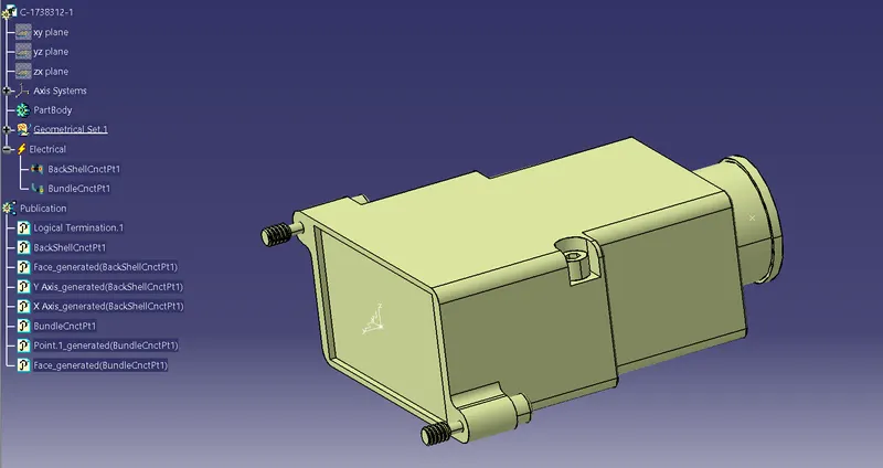
-Import the backshell to catia
-Define the backshell connector and bundle center point.By clicking on the point in the reference element toolbar.
-For the connector side select the between as point type and select the corner point to make middle point
-For the bundle side select the point type as circle/sphere/ellipse center to make center point
-Make axis in the connector side by clicking on the axis in the tools toolbar.
-select the orgin as center point.Allign the axis in a way that y axis away the connector side ,z axis towards the upper side and x axis to the left side.
-Change the workbench to electrical part design.
-Define the cad model to back shell. By clicking on define Back shell in the electrical device definition toolbar.
-set the extra lenght as unset
-Define the bundle connection by clicking on the define bundle connection point in the electrical device definition toolbar.
-Select the face as the repersentation , point as middle point in the center of the bundle and initial condition as face.
-Define the connnector connection by clicking on the define connector connection point in the electrical device definition toolbar.
-select the representation as point in the middle,condact as the face,coincedence as y axis and orientation as x axis.
Q3 Corrugated tubes & Catalogue under “Slit COT” family
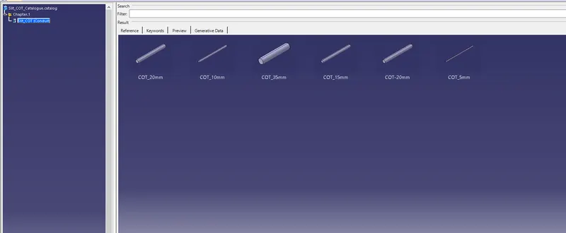
-Open new catalogdocument window and create slit cot family by clicking on add family on the chapter toolbar.
-Create name as slit_COT and type as conduit.
-save the file as Slit_COT_Catalog
-Open electrical part design in the workbench toolbar to create cot
-Click on the Define protection part in the electrical device definition toolbar.
-Select the part in the design tree in the left
-Select the Type as Corrugated tube.Enter the Values of cot.
-Bent radius should be more than 1.5 times the outer diameter.
-click on ok
-Add the cot to the family by clicking on the store device in the electrical device storage toolbar.
-Select the saved cot family catalog and enter the family.
-In the similar way add diferent value cot.