Wiring harness design in CATIA V5 - 3D modeling Week 7 Challenge
AIM - Downloading connectors cad data & define it as Electrical Connector using Electrical Part design Workbench. Define all the necessary properties to Connectors. Routing between the connectors is done using wiring harness assembly.
HARNESS DESIGN PROCESS – Using Physical Architecture, Harness routing and packaging is designed.
· Identify the harness assembly components
· define all harness components as electrical
· prepare harness assembly
· define assembly as electrical assembly
· change tool setting as required
· start routing the bundles
WIRING HARNESS ASSEMBLY STRUCTURE –
CONNECTOR DEFINITION –
· Create / download connector 3D
· Create required geometrical parameters
· Define part as connector
· From electrical part workbench select part as a connector, which states part functions as electrical component.
STEP 1 -
define Bundle connection point
· Create a point on the wire entry side with reference as face normal to the bundle connection point
· This point defines where the harness bundle segment point will end when routed to the electrical connector.
STEP 2 -
d Define connector connection point
Geometry parameters – create a point on the face of the mating side and create a coordinate system at a point created with Y-AXIS should be pointing towards the front face of the connector, same direction as the harness to the connector, X-AXIS should be pointing in the direction towards the locking mechanism of the clip and Z-AXIS should be pointing across the connector from left to right. Can use your own but it should be consistent for mating connectors.
Connector connection point – this point is used for the connection of one connector to another connector.
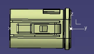
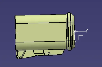
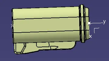
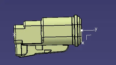
Catalog – create a catalog for connectors after it is electrically defined
Routing – it is done by wiring harness assembly. Prepare product assembly for given harness after designing wiring harness component designs.
Wiring harness product assembly Ensure that all harness components that are needed in assembly are electrically defined with all required parameters before adding them in assembly. All components are placed at desired locations
Branching – creating the wire harness bundle segments by using electrical harness assembly workbench.
Before branching ensure harness geometrical bundle highlighted. It means converting geometric components to electrical component.
Select Create multi branchable document icon to start branching between the connectors.
Input all the required parameters in the branch definition box
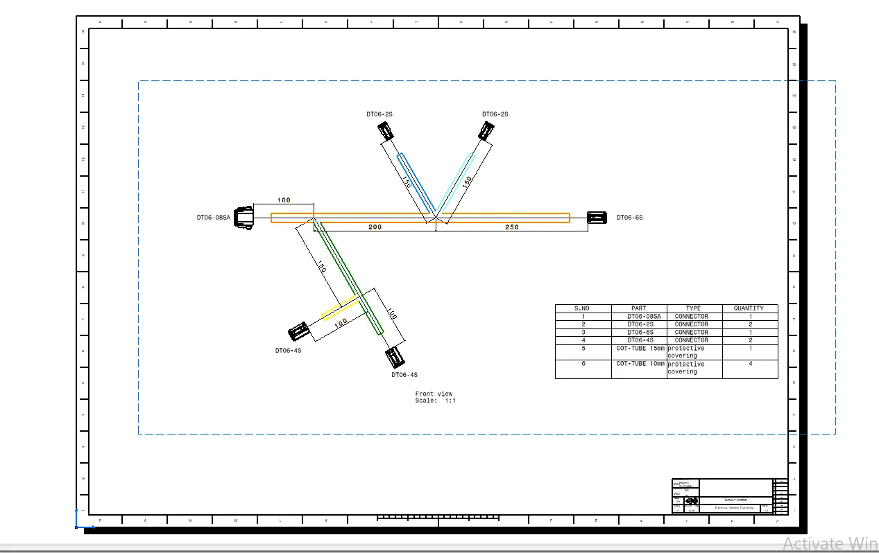
Bend radius is set to 1.4 or greater than 1.5 of diameter of branch i.e,10mm for branching and 5mm for the connectors branched from branch points and ensure that build mode is set to slack.
Create a branch point 100mm from right of DT06-08SA and 250mm from left of DT06-6S and with these branch points branch the connectors.
Create a branch point 100mm from left of DT06-4S and branch the connector with this point.
Creation of protective coverings for the branching. Using COT of dia 15mm for branching and 10mm for the connectors branched from branch points
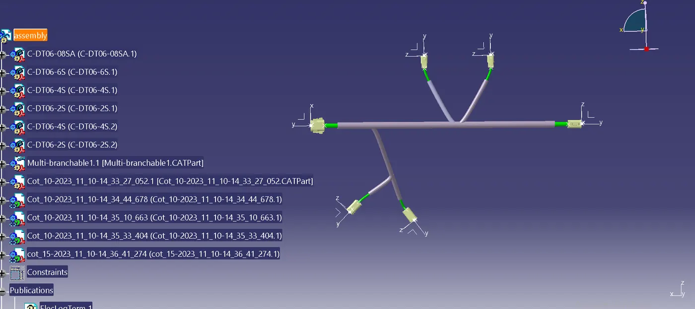
STEP 3 -
Harness Flattening Procedure -
· Harness flattening can be created from the Electrical Harness Flattening Workbench in CATIA V5.
· Create a new product file in the Electrical Harness Flattening workbench and rename it as of our requirement.
· Select the product file and define Flattening parameters to it. And we can rename it as of our requirement.
· Extract the harness assembly into the flattening product by creating vertical windows with Harness assembly product and flattening product files.
· Convert the extracted harness assembly into the flattened harness assembly by using the Flatten commend.
· Rotate the flattened bundle segments to the desired directions using the rotate command and manually update the product to update the changes occurred during the rotate command.
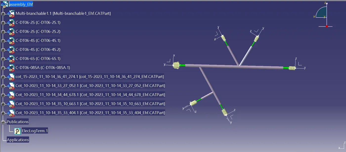
STEP 4 –
Harness Flattening drawing Procedure -
Create a Drawing File for the flattened harness product.
First, we need to make sure that in the flatten parameter settings bundles and protective coverings have different graphical representation which are,
Bundle Segments – Single line representation
Protective coverings – Double line representation
Create a new drawing file in the drafting workbench
Modify the drawing sheet with required parameters.