Wiring harness design in CATIA V5 - 3D modeling Week 7 Challenge
Q1. Flatten the harness assembly completed in “ week 4 challenge”. Place the flattened view on drawing sheet. Ensure bundles with protective coverings has different visuals on drawing view.
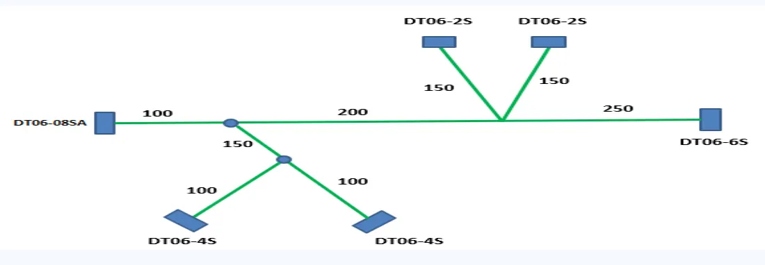
The connectors mentioned above are Downloaded from TE connectivity and all the connectors are electrically defined already in the week 4 challenge.
Steps for Electrical Defining :
Create a middle point on face of the connector.
create an axis system on all the connectors where y-axis should be facing towards mating side.
Define all connectors as an electrical component.
Define connector connection point.
Create Bundle connection point.
For wiring harness and protection covering ,
Create a sketch as per the location of the connector in the figure provided.
Place the given connectors on their respective location .
For Harness and protection covering , part is taken into electrical harness assembly where by using Multi Branchable command wiring harness is done and after that protection covering is done on all the branches .
for the point in between a branch point is used for the creation of another branch.
A catalogue is already created of different sizes of protection covering through there Wire catalogue is used for covering.
ELECTRICAL HARNESS FLATTENING.
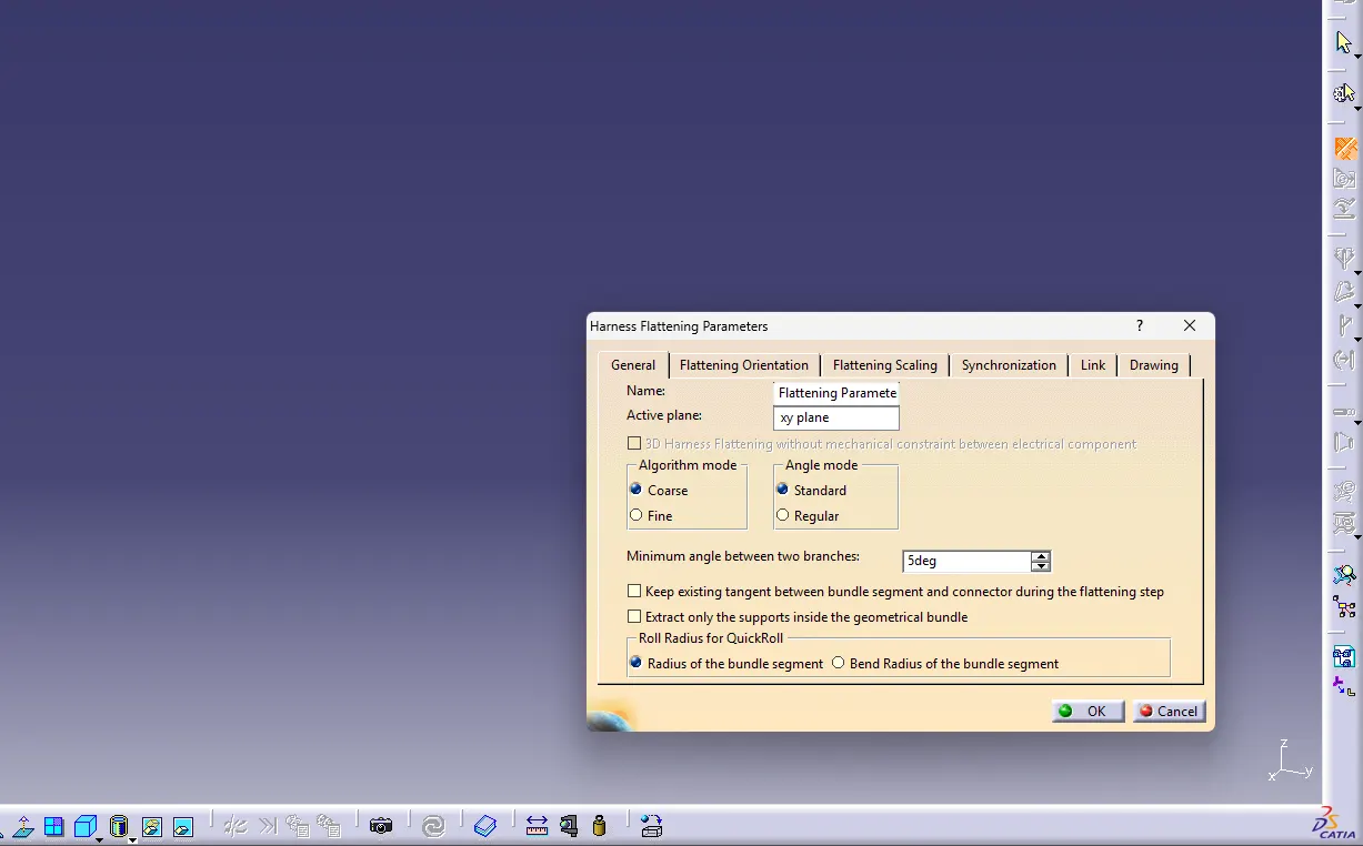
Before moving to electrical harness flattening , some parameters is to be defined .
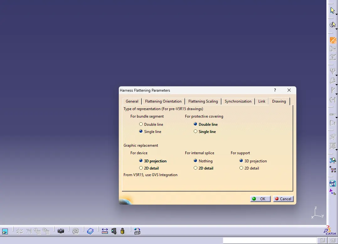
Here Single line and double line are used for the representation of bundles in the diagram.
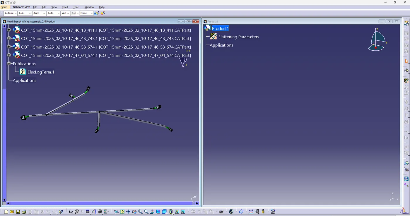
For flattening two windows are opened vertically through which flattening parameters are imported and also the cat product part.
then after Flattening command is selected with the plane selection and all the branches .
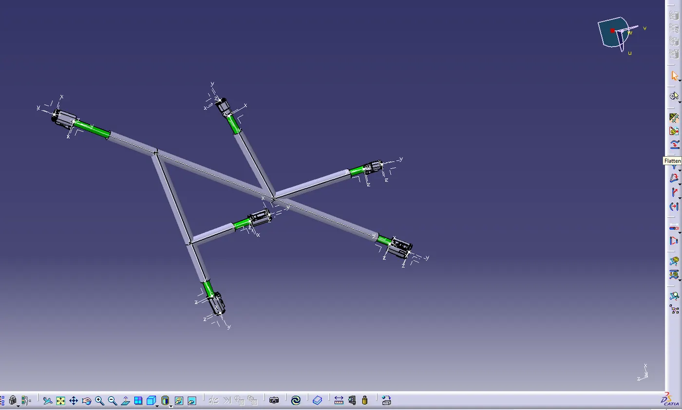
on the right panel all the flattening tools are available in which rotate command is used to rotate the branch as per the required diagram.
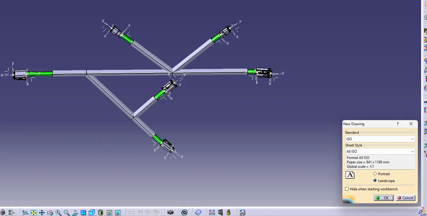
A new file created in the name of Drawing where its parameters are selected as per the ISO size requirement.
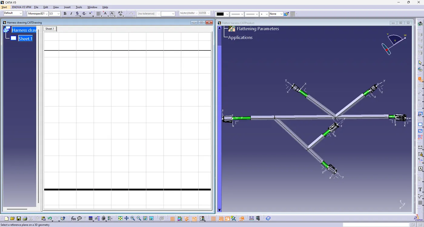
Here again both the windows are opened vertically so that the Cat part is imported using front view plane command.
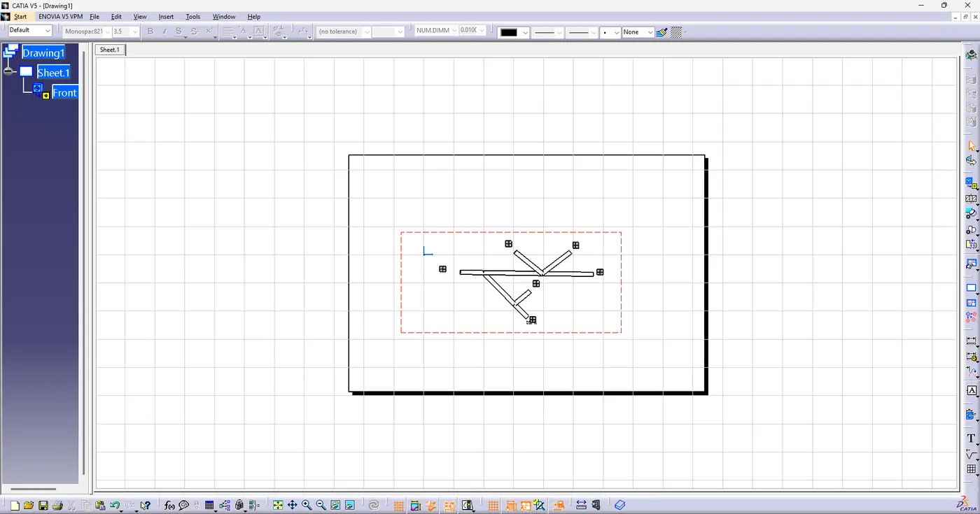
Here the drawing is extracted and converted into diagram , where as the box are representing the connector as in 2D diagram.
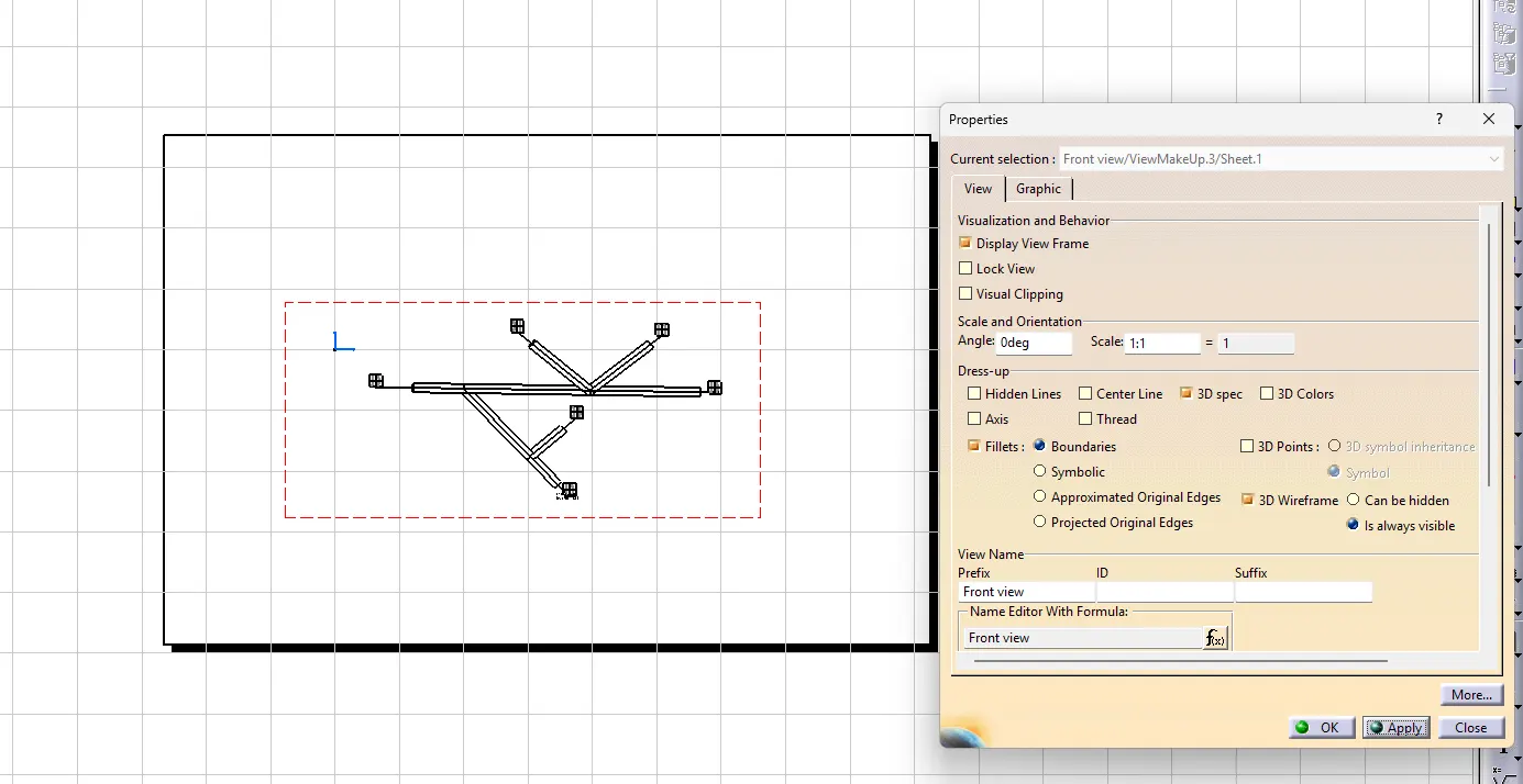
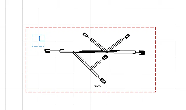
After changing the parameters into 3D diagram the connectors are visible one can change the color as well .
Earlier parameter was set for single line as wiring and double line for Protection covering.
Here an extremity of 30 mm given on the end point of the wiring connector so that difference is visible and also for the easy fitment.