Wiring harness design in CATIA V5 - 3D modeling Week 7 Challenge
FLATTENING CHALLENGE
AIM:
To Flatten the harness assembly completed in “week 4 challenge” and Place the flattened view on drawing sheet. To Ensure bundles with protective coverings has different visuals on drawing view.
GIVEN DRAWING:
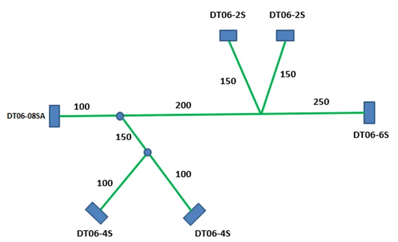
From the following data the harness assembly has been created.
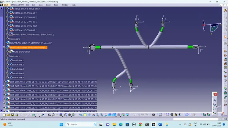
STEPS TO FOLLOW:
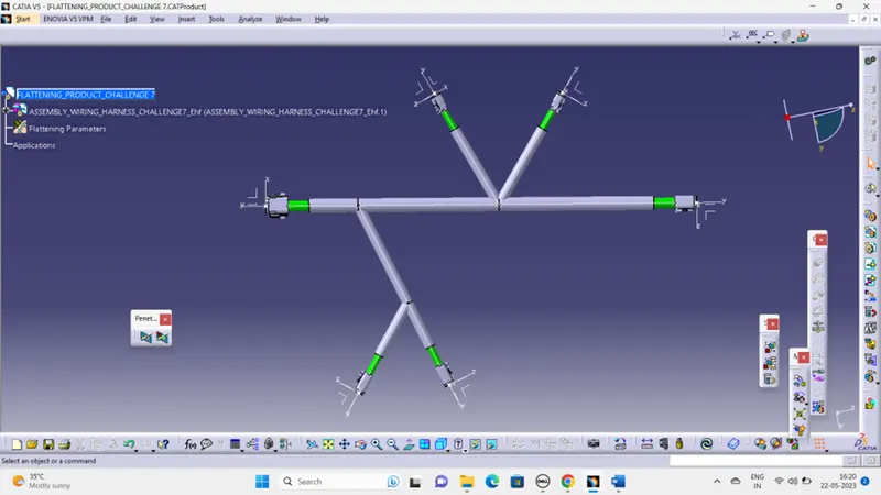
- We go to the harness flattening workbench and define the flattening parameters.
- While defining the harness flattening parameters in the drawing menu single line is selected for bundle segment and double line is selected for protective coverings in order to differentiate between the wire bundle and cot tubes in drafting.
- We use the extract command to bring the harness assembly to the flattening workbench here.
- Then wire harness assembly is imported to the Wire flattening product file with 'EHF' extension added to the geometric bundle assembly name
- Choosing a suitable plane to flatten the harness assembly.
- Bundle segments are rotated at the required angles. The harness assembly is then drafted.
- Flattening parameters are defined in order to make the bundle and the corrugated tubes visible in the 3d drawings.
- Save the product file using 'Save management' option so that all the related product files and part files are stored in single directory.
FLATTENING PRODUCT:
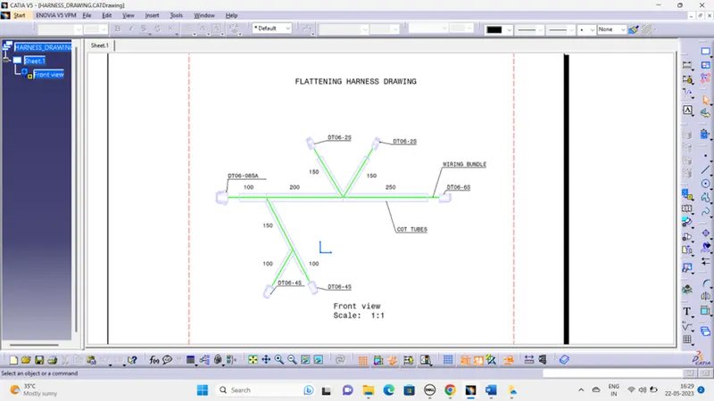
DRAFTING:
- Create a new drawing file and save the file in the same location.
- Add the front view of the harness assembly Here I select the surface of the connector. and orient the view as per the requirement.
- Go to the properties of the view and select the '3D Wireframe' on and ' Is always visible' option in order to see properly the Wire bundle, connectors and the protection coverings.
- Then Naming the connectors and cot tubes.
- To add the length details of the bundle segments.