Wiring harness design in CATIA V5 - 3D modeling Week 7 Challenge
Harness Assembly Flattening using “Flattening harness workbench” in CATIA
The Harness assembly to be flattened in the “flattening harness” workbench should be as per the below electrical schematic diagram,
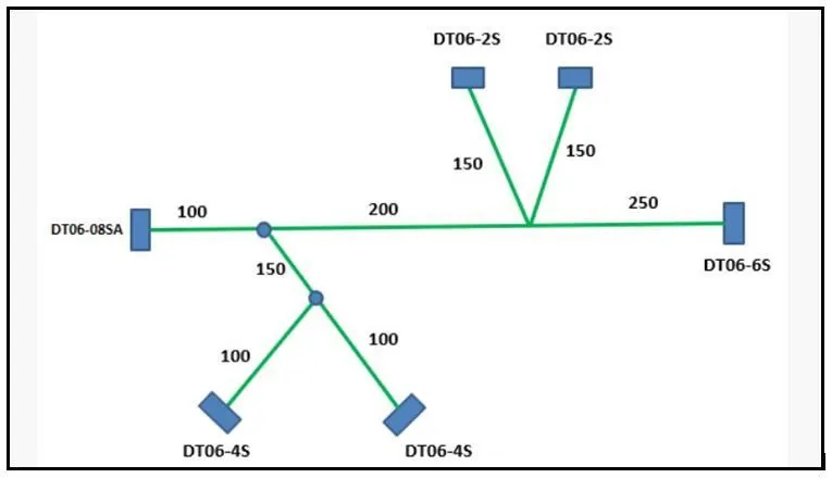
The Above Harness is assembly is saved in a new product file, which consists of the subassemblies as shown below,
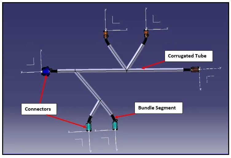
- Geometrical Bundle: - The Geometrical Bundle consists all the connectors, and its respective geometrical parameters.
- Multi-Branchable Document: - The Multi- Branchable document consists of all the Bundle segments and protective coverings used to connect the connectors to create the harness assembly as per the above diagram.
- Publications: - All the electrical data gets saved in the Publications for establishing the electrical parameters
The Electrical harness assembled view as per the above diagram is shown below,
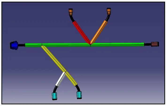
As the above electrical harness assembly has to be flattened and viewed on the drawing sheet, the protective coverings have been shown in different colors, as shown below,
- Electrical Wiring Harness Flattening
The Flattening of the wiring harness assembly has to be initiated prior to setting of the flattening harness parameters in the flattening harness workbench in CATIA.
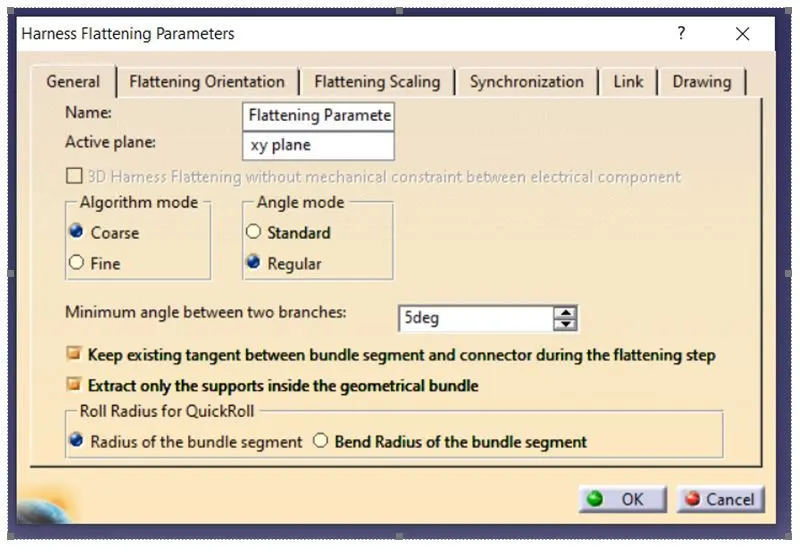
The Flattening harness parameters mainly includes the selection of “PLANE” to view the harness assembly and make changes to the flattened bundles with respect to the selected PLANE OF VIEW.
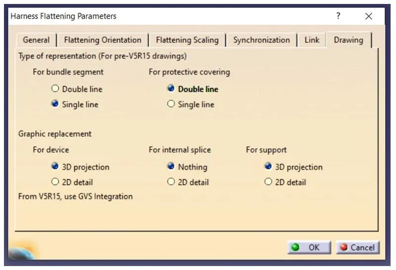
The Second most important in Flattening harness parameter is representation of the flattened view in drawing sheet, such that the different parts of the wiring harness bundle assembly are identifiable with respect to the electrical schematic diagram for parts like bundle segments, connectors and protective coverings.
The Main Flattening harness parameters to be set are shown below,
- General TAB
- Drawing TAB
Once the flattening parameters are set then, a flattening harness file gets created in the flattening harness workbench.
We have to now select the respective harness assembly for which flattening process has to be executed.
The following steps given below, explains the steps for flattening the harness assembly,
- Keeping the flattening harness file opened in the CATIA window, we have to next open the harness assembly file, for which flattening has to be done.
- Next, we have to make both the file to be opened in vertical windows, in order to extract the harness assembly from the harness assembly file to flattening work bench, where the harness assembly will be flattened.
- We have to select the extract command in flattening workbench and select the harness assembly product file to make the harness assembly transferred to flattening workbench, along with its all-defined supports.
- Once the extraction of the harness assembly file to flattening workbench is completed, then the harness assembly file gets a file extension ending with “Ehf”.
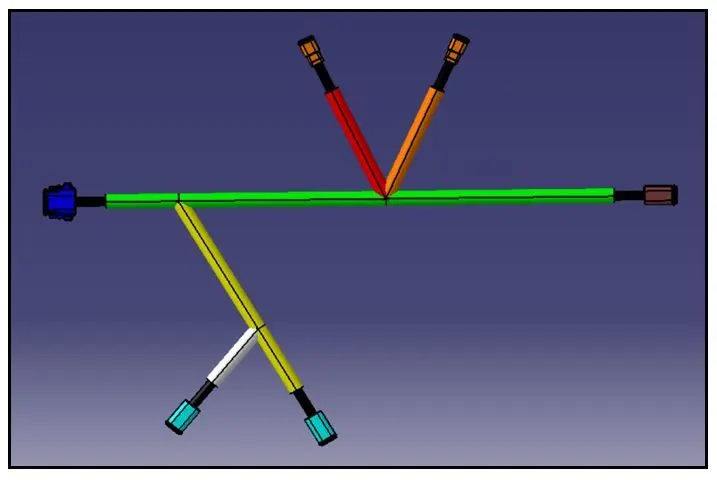
- In the Flattening workbench, we have to select the flatten command and make the respective harness assembly flattened meeting with the set flattening parameters, which were defined prior to extracting of the harness assembly file.
- In the Flattening workbench, there are major commands used to represent the flattened harness assembly in accordance with the electrical schematic diagram. The commands used are: - “Rotate”, “Quick-roll”, “Straighten”, “Arrange junction” etc.
The Flattened procedure performed for the harness assembly is shown in below figure,
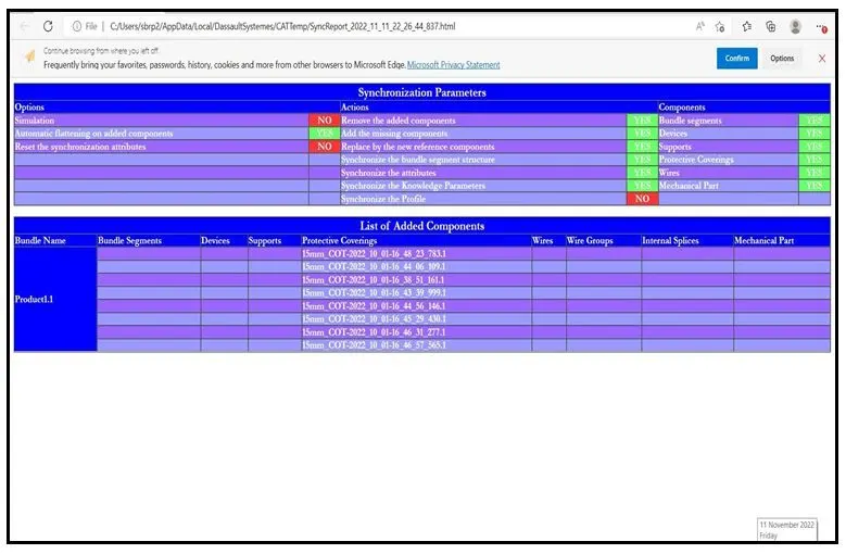
- The protective coverings get updated on to the flattened harness assembly from the native file (i.e., harness assembly file) by selecting the “synchronization” command in flattening workbench.
The Synchronization report gets generated, which explains the matching of the changes updated from the harness assembly file to the flattened assembly file.
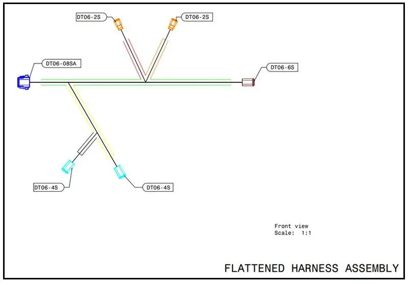
The Final Flattened assembly is then represented on to the drawing file, by setting certain view conditions, in order to identify the different parts of the flattened view of the harness assembly.
The Drawing of flattened view of harness assembly is illustrated by representing the single line has the “BUNDLE” and the double lines has the “PROTECTIVE COVERINGS”.
The View of the flattened harness assembly will be normal to the front view which is default in representation.
The necessary annotations to the parts, BOM display and other detailing’s are provided on to the drawing.