Wiring harness design in CATIA V5 - 3D modeling Week 7 Challenge
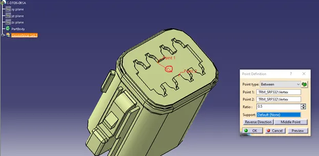
defining step -1 ;create points &axis system at center on connector connection side in part desgin workbench &ensure y axis normal to faces x axis along he locking direction
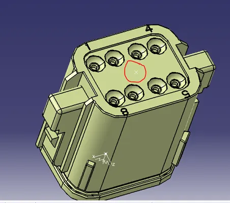
step 2 - ; create point at center on bundle connection sie
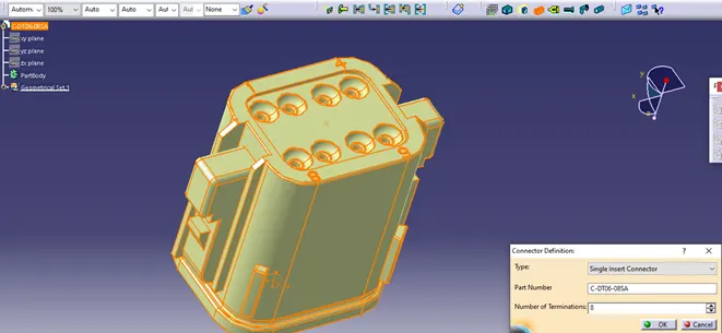
step 3 ; switch into eletrical part desgin work bench and define it as eletrical component by using deine connector command & click on part give input 8 in dialogue box for number of termination ponits then click okk
step 4 ; use define connector connection point command and select inputs
step -5 ; use define bundle connection point comman and select inputs
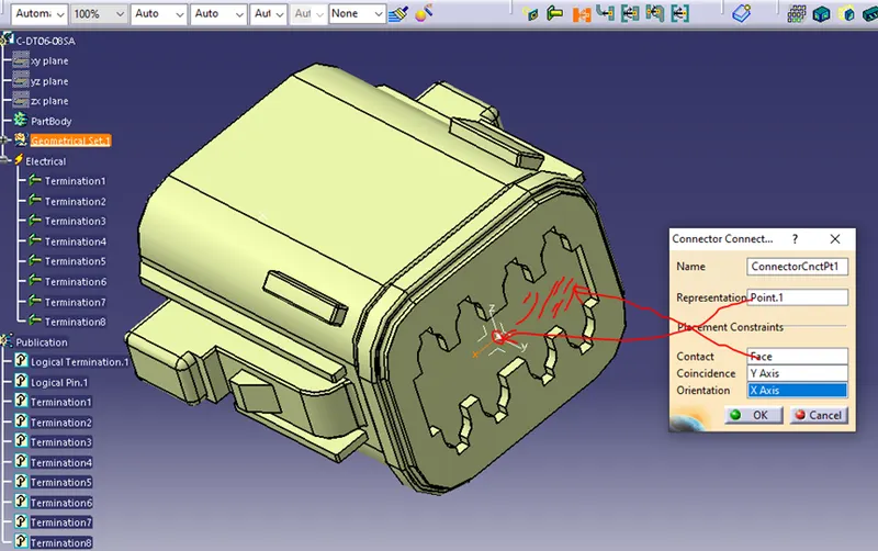
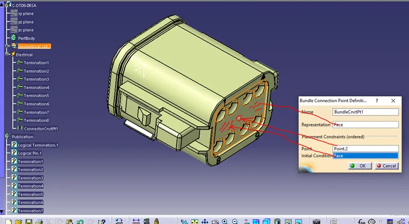
follow above same steps to define other connectors &give respective termination points 4,,6,2 while define connetors for DT06-4S,DT06-6S ,T06-2S
now to route wiring to the connectors ,call all the defined connetors into normal assembly design work bench &arrange these connectors asn per given layout with manipulators or axis system
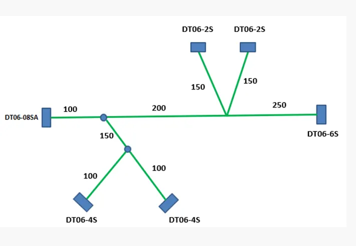
create line as shown image below and end of line will be at 550 mm from origin ,then with snip tool arrange connector (C-DT06-6S)at this end of line as per layout
angle assumed for branches and layout diagram constructed with ponits ,line &axis system
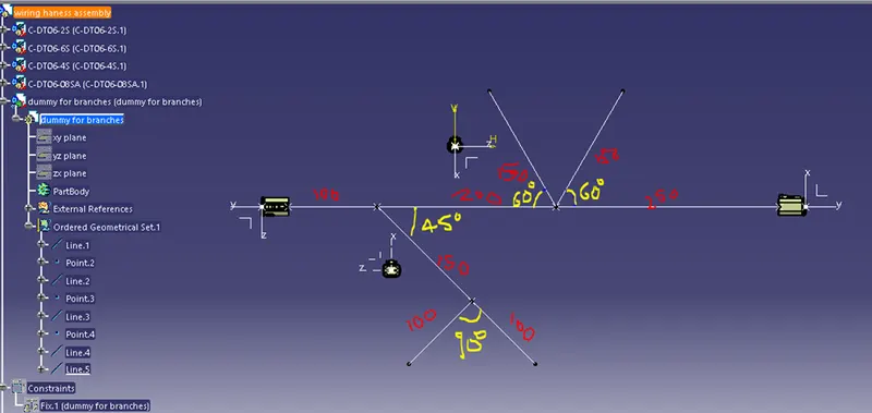
now arrange all connetors at specified location by manipulation and snap command
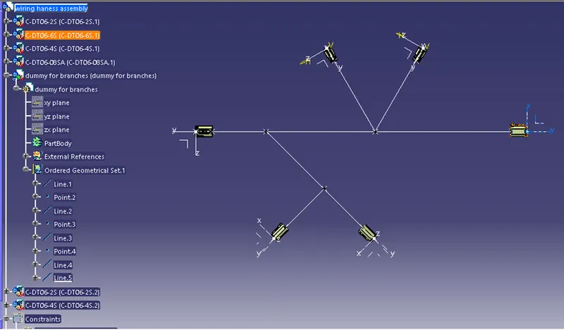
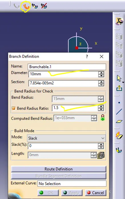
- now switch into electrical harness assembly workbench *with geomtrical bundle command convert normal assembly into electrical assembly ,then click on multi branch able document command give highlighted inputs as shown in image (diameter &bend ,radius ratio )get into route defintion and select these two connectors in image below
- now with add branch point command add branch check below image
- then with branch defintion add branch
- then with branch defintion command inroute defintion add remaning branhes
- now add protective coverings
- use light protective covering command to add protective covering and select throught document COT tubes of higher diameter now bundle diameter is 10 mm so choose 15 mm diameter COT tubes as protective covering.
- then click on end extrimtes nearer to connectors and give value of 30 mm away from connector
- repect same for other branches also
now ,to prepare 2d drawing switch intlo eletrical harness flattering work bench
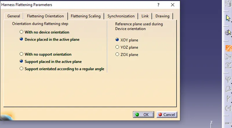
in flattening orientation keep as it is default plane
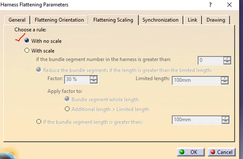
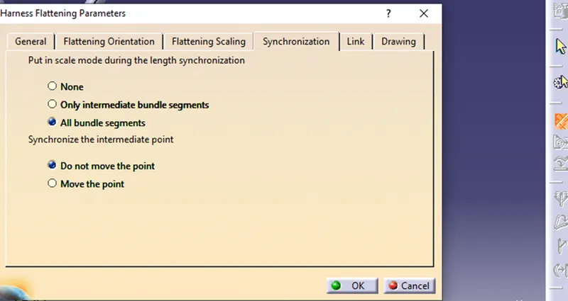
in scaling coose with no scaling .we have scope to scale further
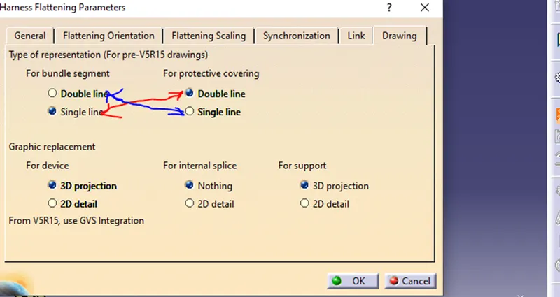
in drawing setting select contrst option for bundle and protective covering to understand easily while prepare drawing
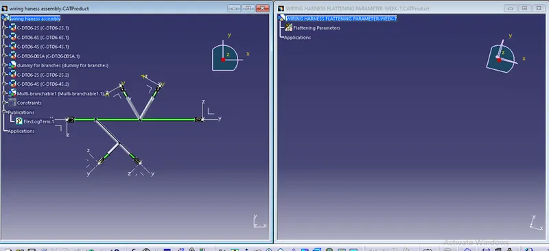
now save this product file &also save the created harness assembly product file into same path
and then using window till vertically command to select created wiring harness assembly for flattend assembly ,click on extrat command .then click on harness assembly and extract into product file (wiring harness flattening)
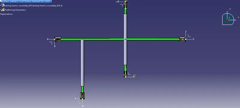
then it will converted as shown in image below
now start preparing drawing from start -mechanical design -drafting
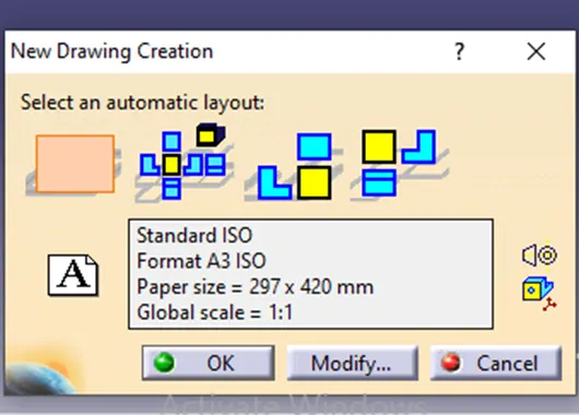
activate front view and then switch into flattening window for view
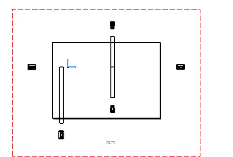
now bundile segments are visualzing go to view properties and activatee 3d wire frame option
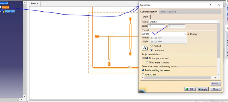
- now change sheet size to fit view into sheet ,now it is A3change to A1 ,A2,check approprites sheet size
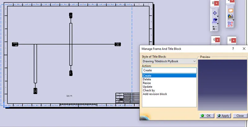
- now go to edit -sheet background and click on frame and title block