Wiring harness design in CATIA V5 - 3D modeling Week 5 & 6 Challenge
Aim:
1.route the two electrical harnesses as per the given layout and interconnect them as a single harness assembly.
2.check for bundle continuity, and the bundle warnings, and then provided annotations for the final harness assembly.
Given master section:
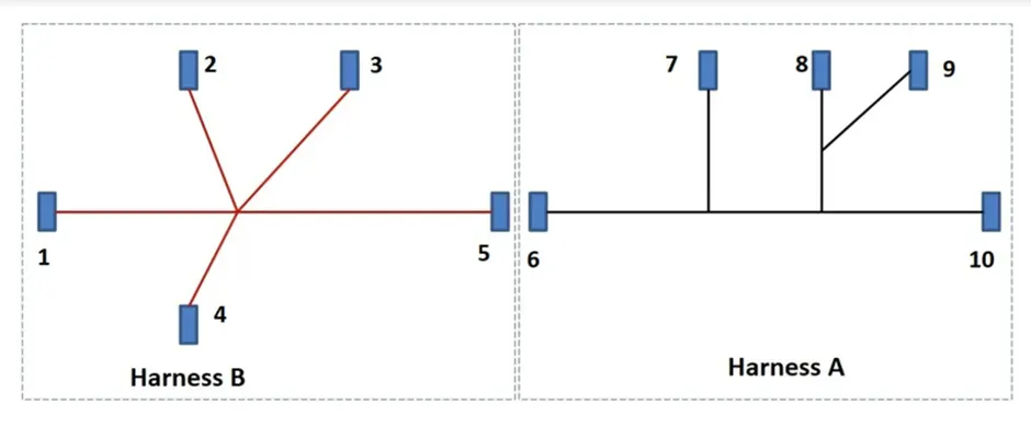
Harness assembly procedure:
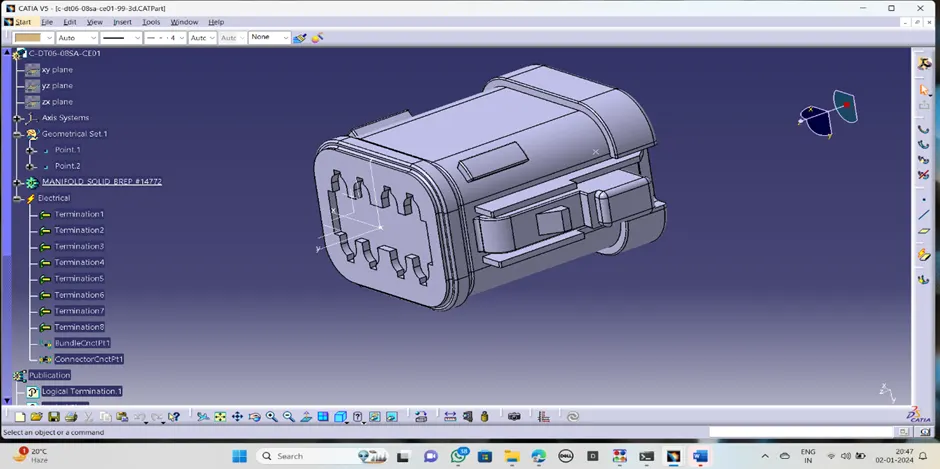
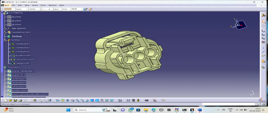
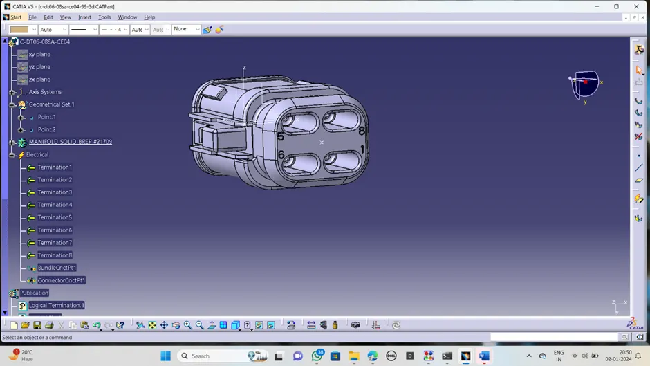
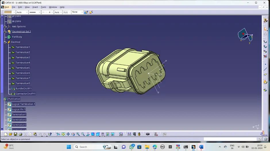
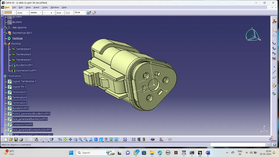
1.Procedure for define connectors as a electrical equipment:
· Download the cad files from given link above mentioned and open in the Catia v5
· Define the geometrical properties in the part work bench like points and axis system
· Now switched into the electrical part design to define it as electrical connector
· Click on define connector and click on connector, give appropriate terminals presented to it
· Click on bundle connection point to create the bundle connection point in the bundle entry side by choosing appropriate face and point.
· Click on connector connection point to create the connector connection point connector fixing side by selecting the coincidence, point, rotation and contact.
· Now the connector is becoming the electrical component to use in wiring harness.
· Procedure is same for all above-mentioned connector.
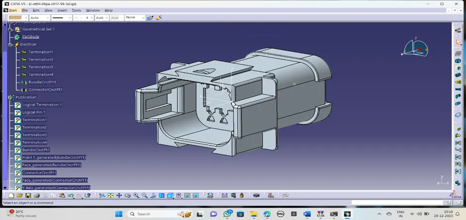
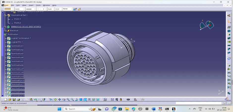
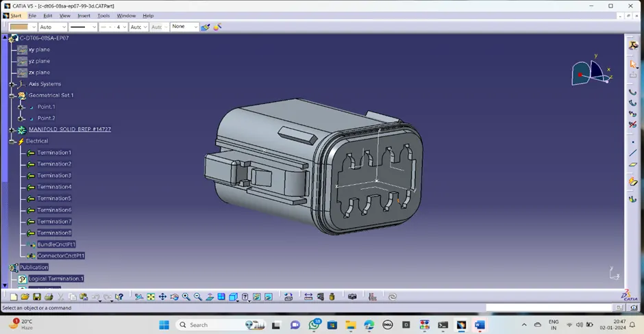
HARNESS ASSEMBLY-A
After defining all connectors as a electrical components now create the product file and import the related connectors in to the file.
Now arrange the all connectors in their respective position as shown in given master picture by using manipulation and other positioning tools.
After that switched into the electrical harness assembly .
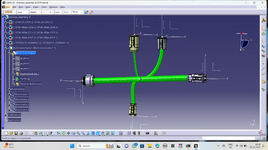
· Make the assembly into electrically define by clicking on geometrical bundle.
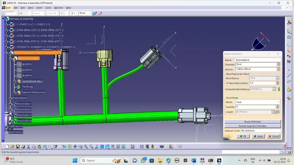
· Now route the all connectors using the multi-blanchable command.
· Create the branch point where the route want to divide and to give route to the other connector.
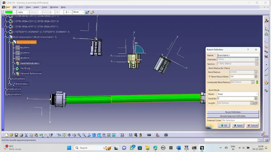
· Create the route between them by using branch definition.
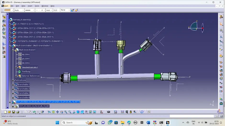
· Apply the protection covering if needed in the particular area by browsing the covering tubes in the catalogue.
HARNESS ASSEMBLY-B
In this assembly also follow the similar procedure followed in the harness assembly-A but the import the respect part connectors available in the B assembly.
· Make the assembly into electrically define by clicking on geometrical bundle.
· Now route the all connectors using the multi-blanchable command.
· Create the branch point where the route wants to divide and to give route to the other connector.
Final harness assembly:
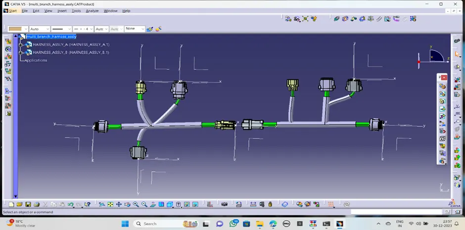
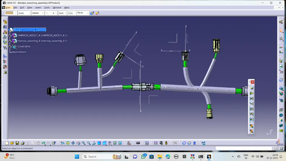
Now again create another product file and insert the both harness assembly product files in to this product to assemble together.
Arrange the both assemblies in proper position and coincide the connectors where the connector has to connect.
Go to the electrical assembly design work bench,
Click on the connector connection command and click on the connector of any one assembly first, then click other one, there will show the connector connection point activation. Click on ok to connect together.
Bundle error:
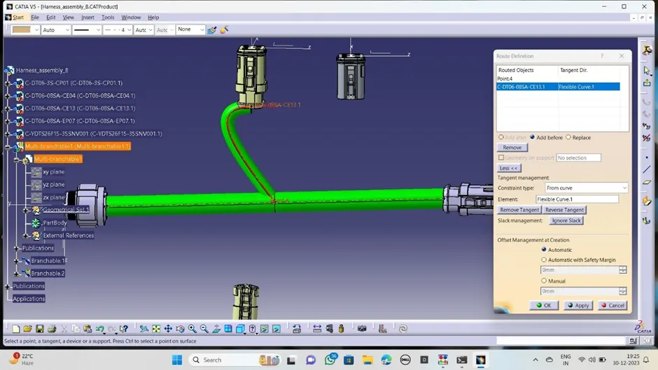
In this step, we checked the bundle warning in harness A and B
In this case the bundle shows the error in bundle diameter and revere direction while harness creation.
This error corrected by the changing the bundle diameter to the 5mm and changing the direction of the bundle creation from the connector side. then the bundle error solved and created correct bundle between the point and the connector.
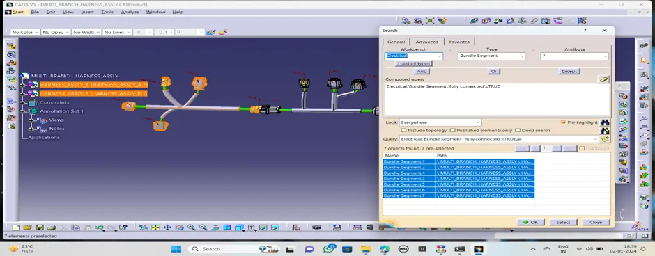
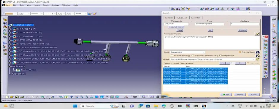
Connectivity check:
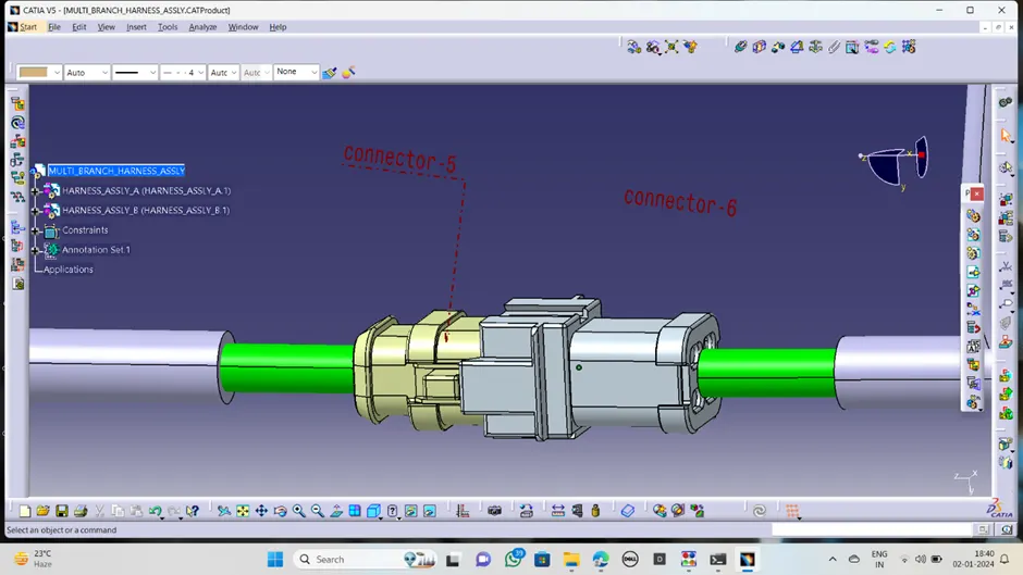
Annotation:
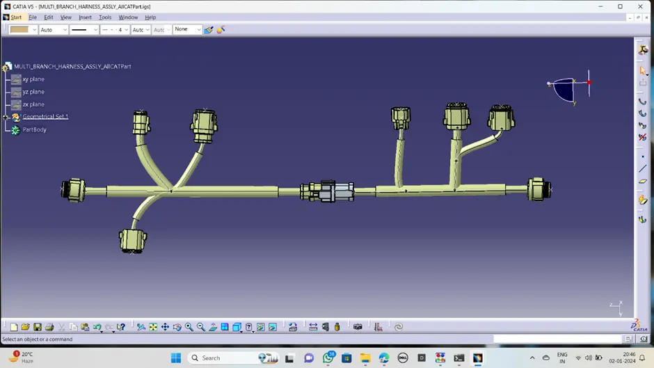
Part file converted into igs file:
The harness assembly file converted into the IGS format.
For that we have follow this steps:
Go to mechanical assembly>tools>generate cat part from product.
Then click on the harness assembly file converted into the igs file
Conclusion:
in this challenege completed the multiple harness branches assembly together as a single harness assembly design,created the annotation and converted the assembly part file into the igs file.