Wiring harness design in CATIA V5 - 3D modeling Week 5 & 6 Challenge
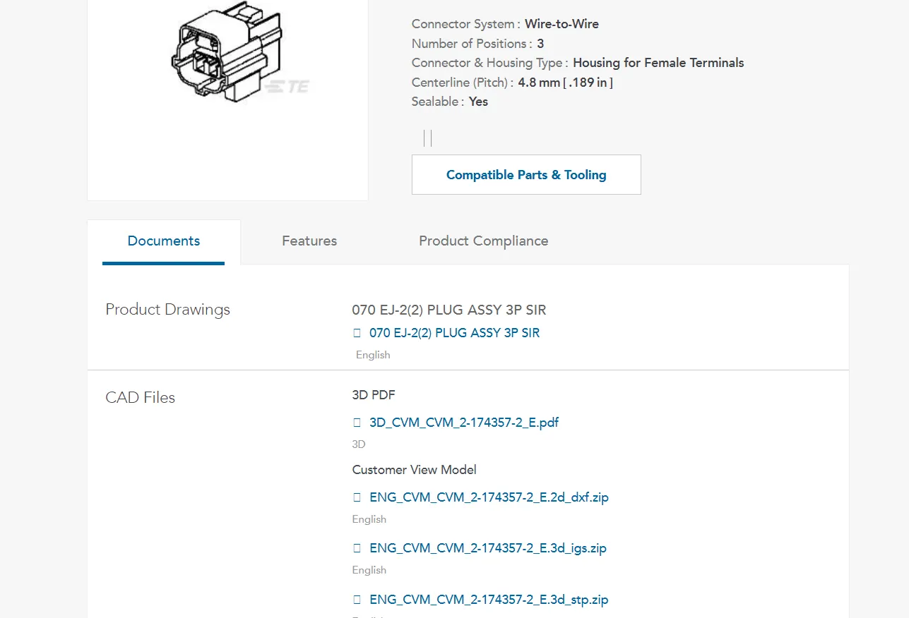
- when u click on the link. it takes to the TE connectivity page as shown the above fig.
- then download the ign files.
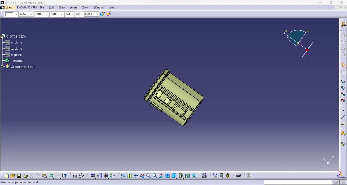
- then open the downloaded ign files in the catio.
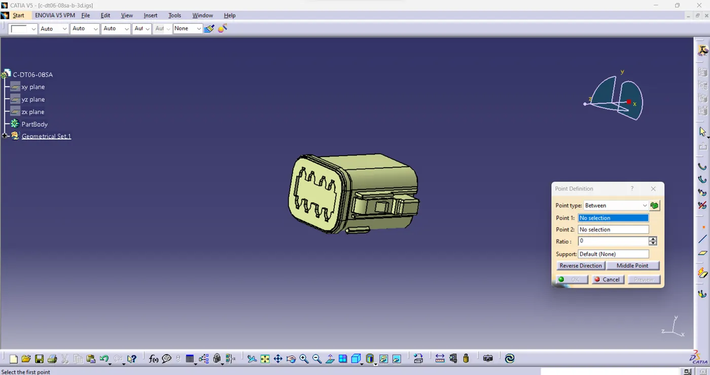
- create a point at two faces of the connector at the center.
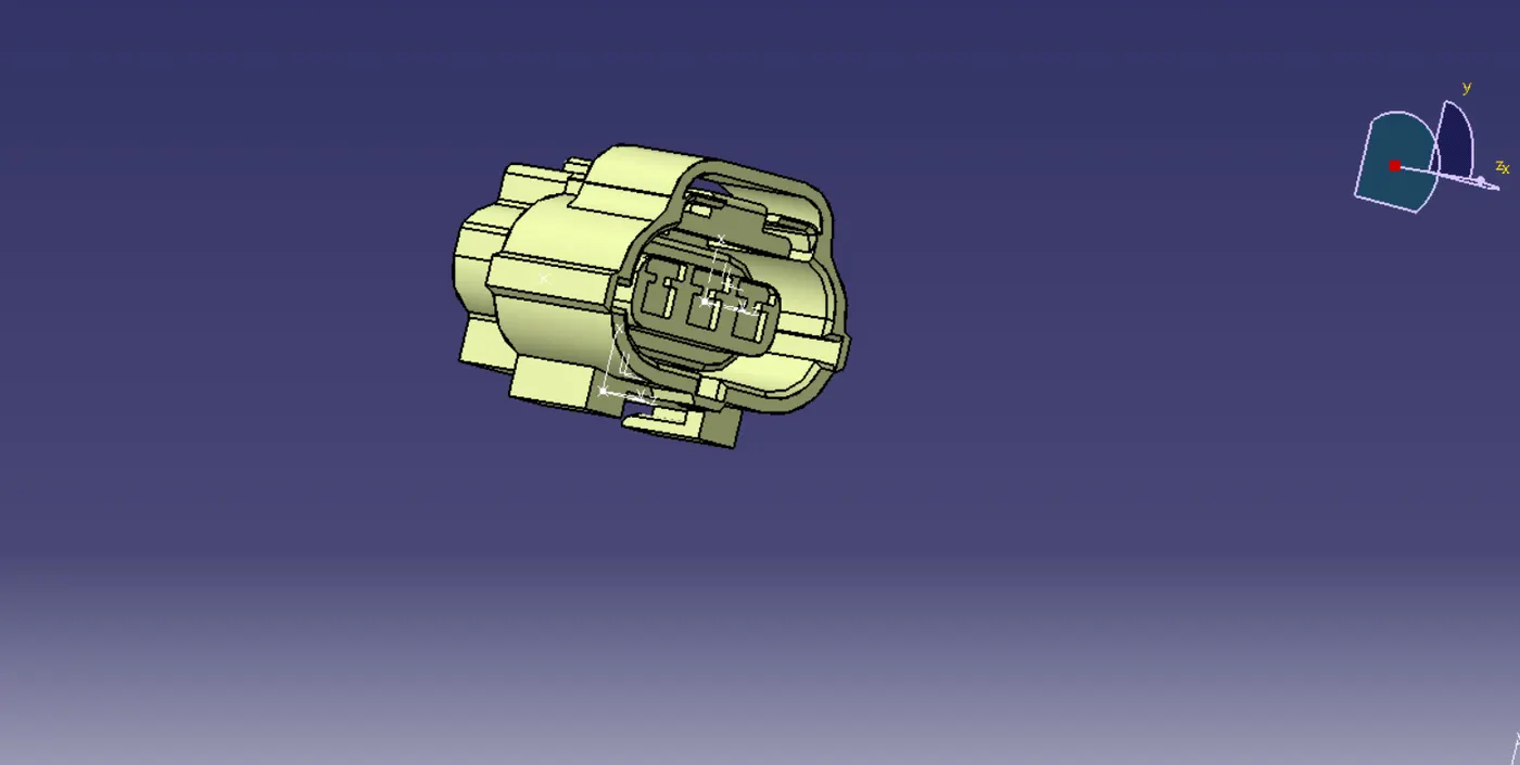
- axis system is create at the connector end as shown in above fig.
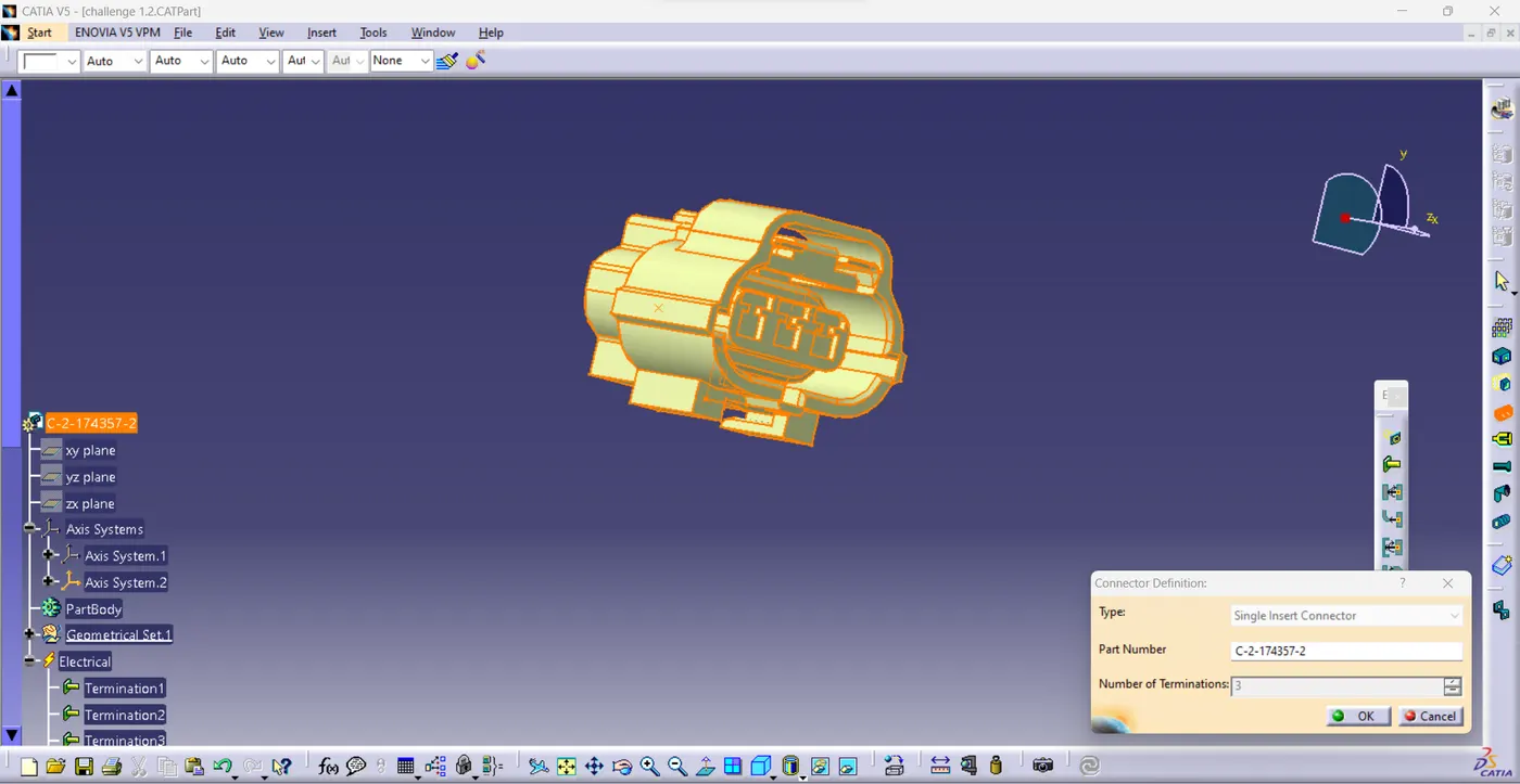
- define the component in to electrical component by using connector definition.
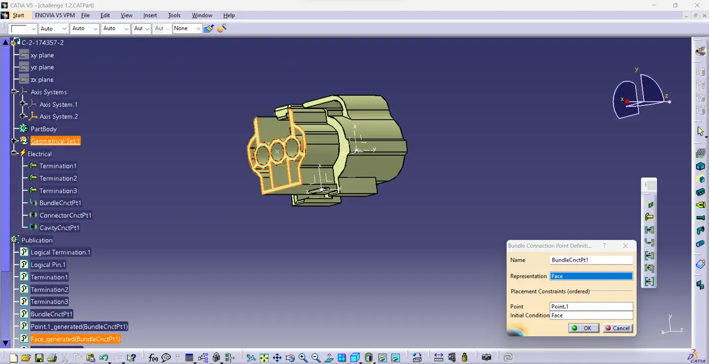
- create the bundle connection point at the another side of the connector by using define bundle connection point as shown in above fig.
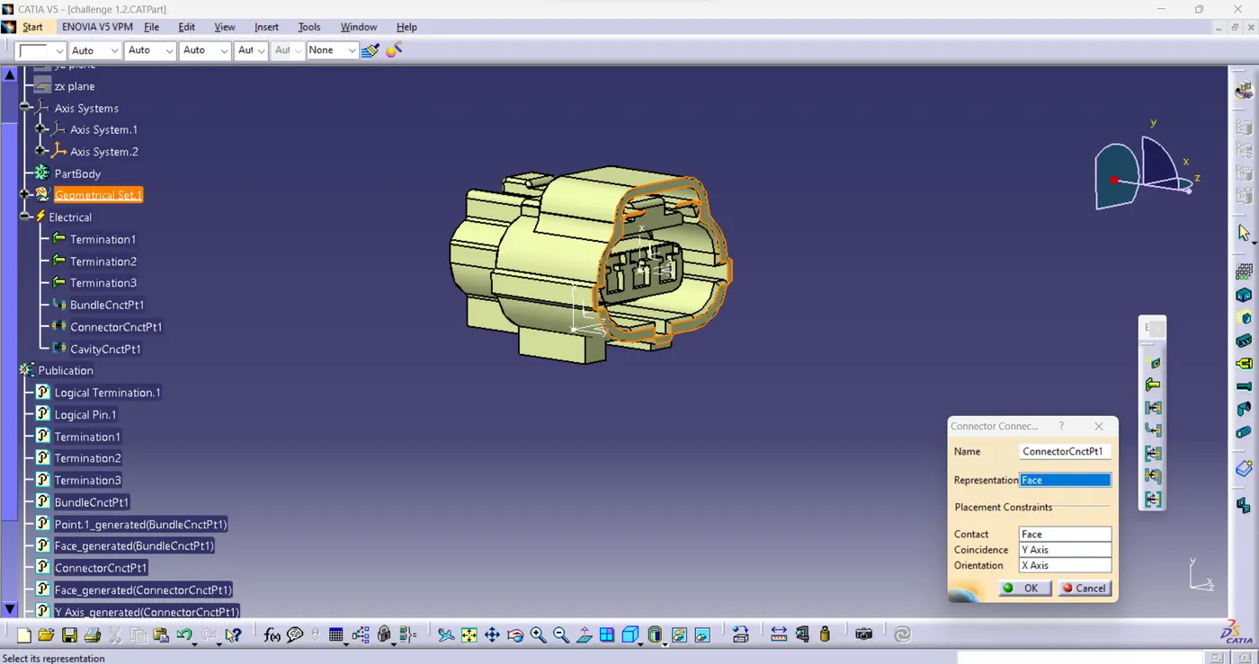
- create the connector connecting point at the connector side of the connector by using define connector connection point as shown in above fig.
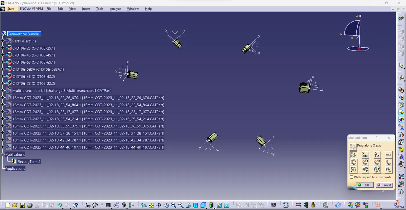
- using manipulation, place the electrical components at required position as shone in fig.
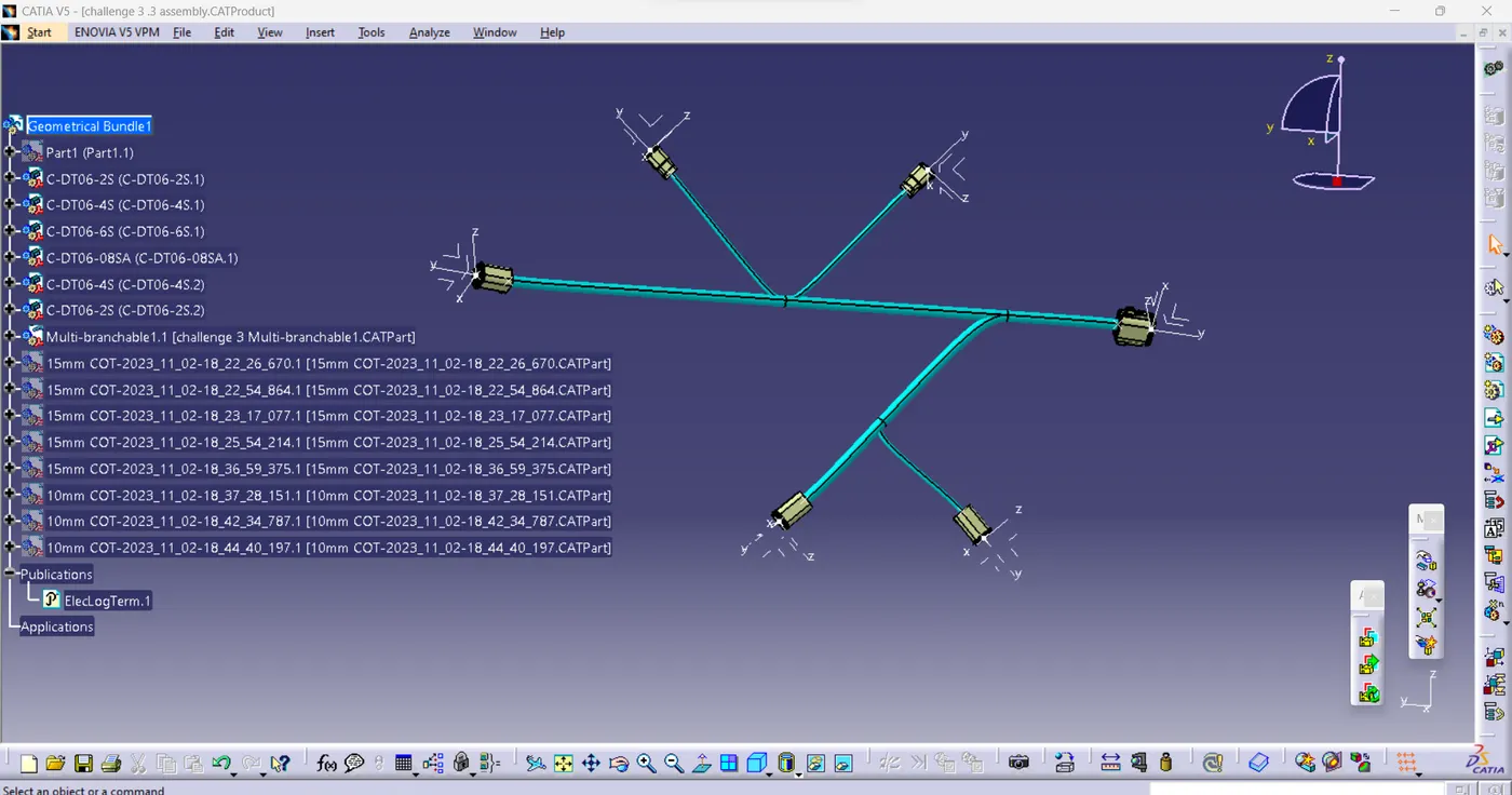
- using multi branchable, connect the connectors
- after bundle is created, Add bundle point at required position at the bundle.
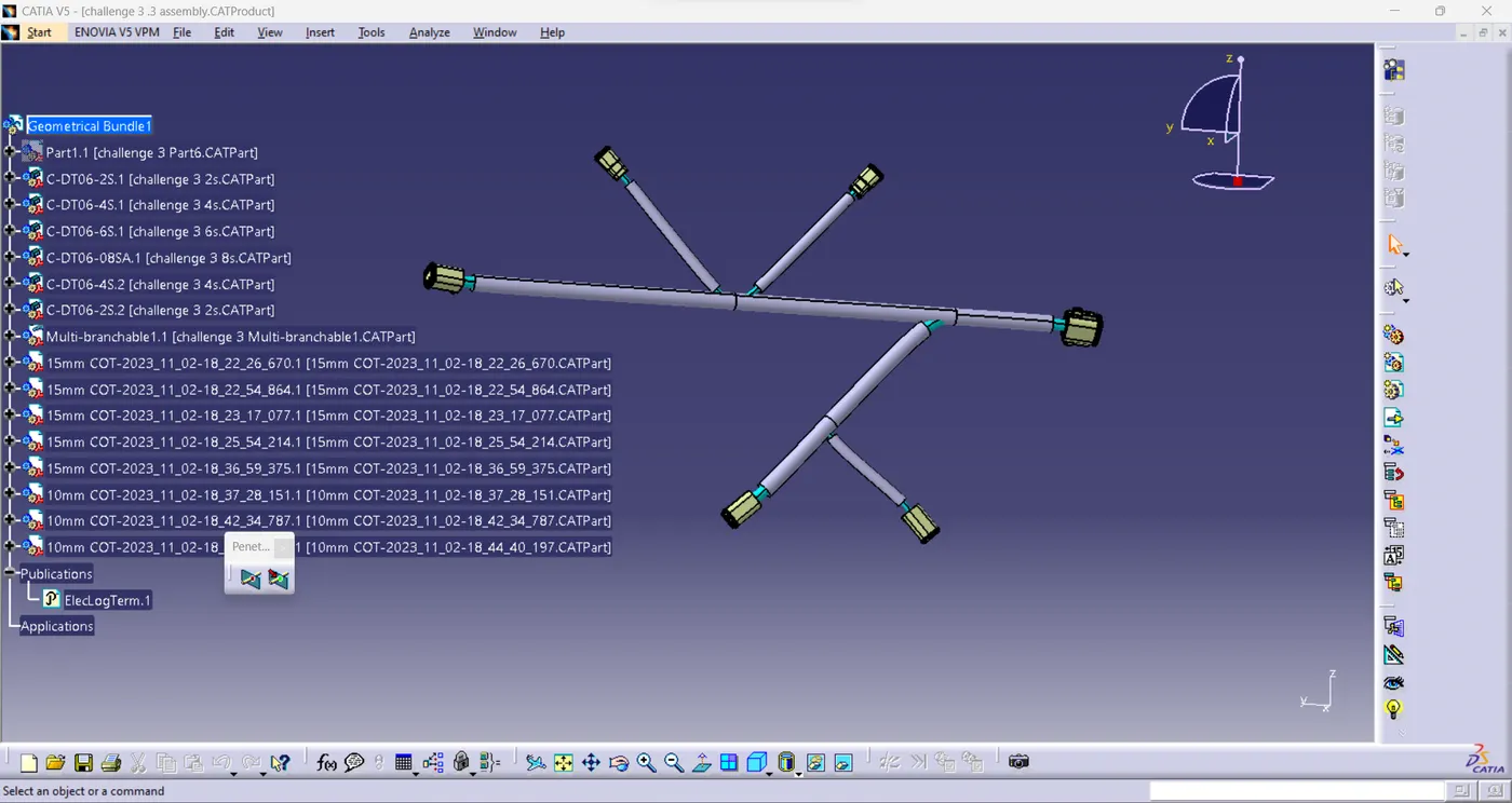
- add protetive covering to the bundles as showen in fig.