Wiring harness design in CATIA V5 - 3D modeling Week 5 & 6 Challenge
Wiring Harness Design Using CATIA-V5:
Aim:
To Route the following harness layout in Electrical workbench. Make assumption for harness bundle diameters. Use the connectors provided. After completion of routing.
1. To Download The Given Connectors .
2.Define The geometrical parameters to the connector. Create connector connection point. create bundle connection point. Create Axis system in Connector Connection Point. Then Define It as Connector In Electrical part workbench. Then Define Connector Connection point & Bundle Connection point.
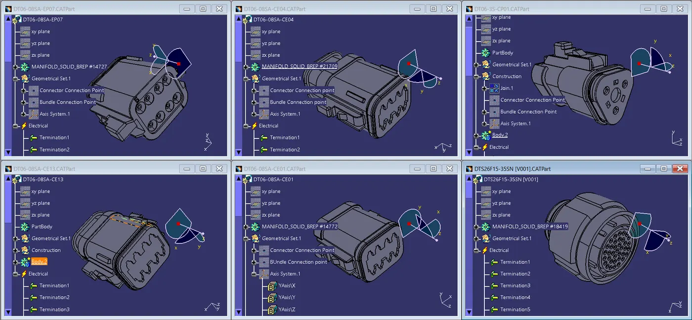
3. Create a new Product Named= Wiring Harness Assembly.
4. Then Create a Product Under the Wiring harness assembly Named= Assembly Harness A & Assembly Harness B.
5. Then Create a Product Under the Wiring harness assembly Named= Metal Plate.
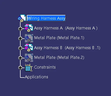
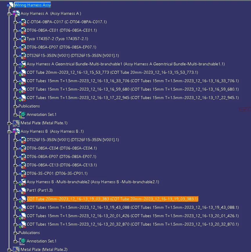
6. Then Insert All the connectors in to Assembly Harness A & Assembly Harness B.
7. then convert the Assy Harness A&B Product To Geometrical bundle in Electrical Harness Assembly workbench.
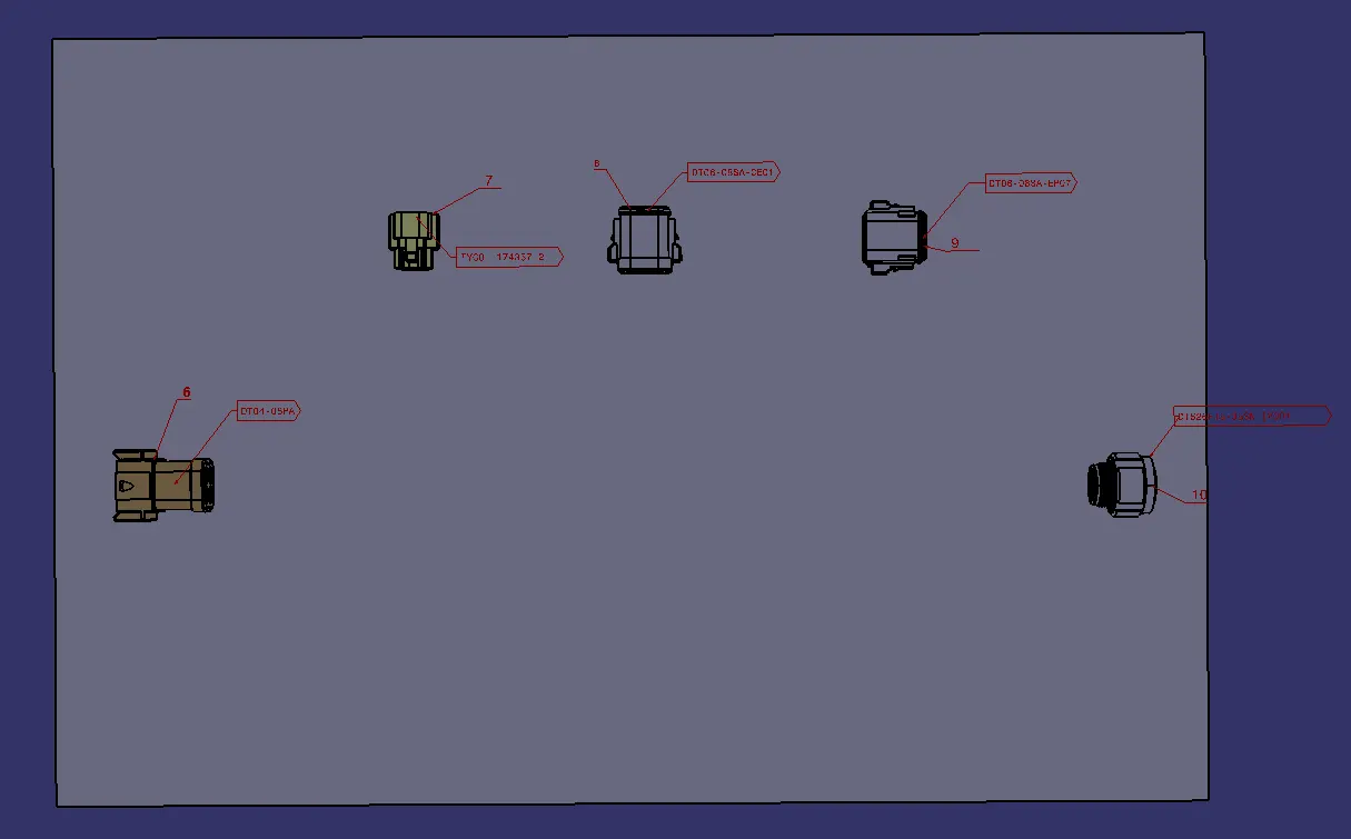
8.Ive Created a Metal Plate As Referance Base To Position And Placing the Connectors.
9. I Have Positioned All Connector In Place With Mechanical assembly workbench.
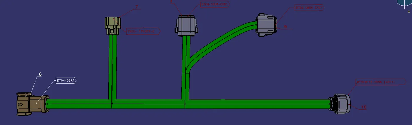
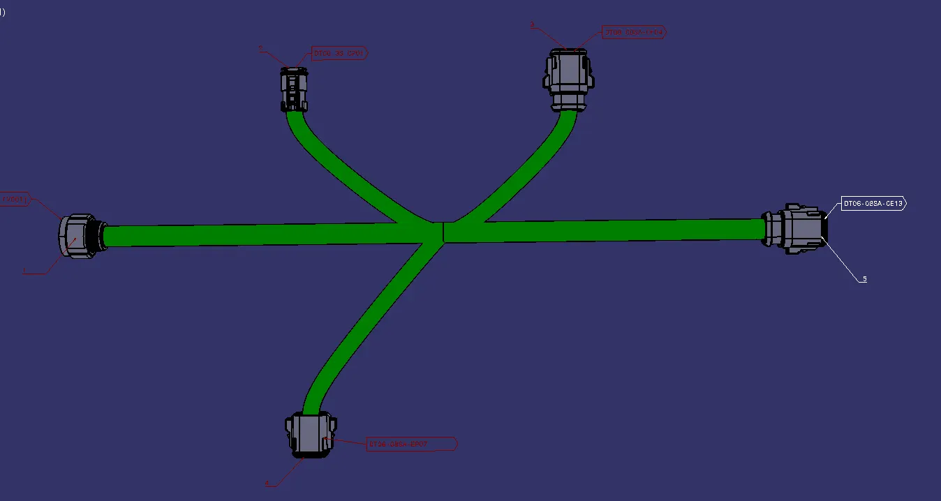
10. Then Create A Multi-Branchable.
Harness-A
Harness-B:
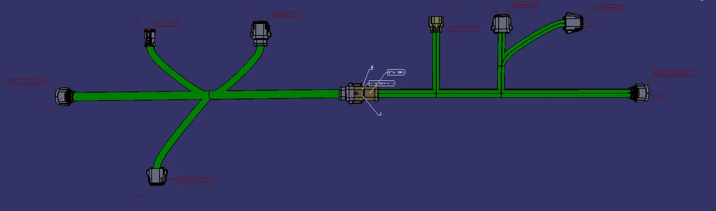
11. Then Connect Harness-A&B in Electrical Assembly Design.
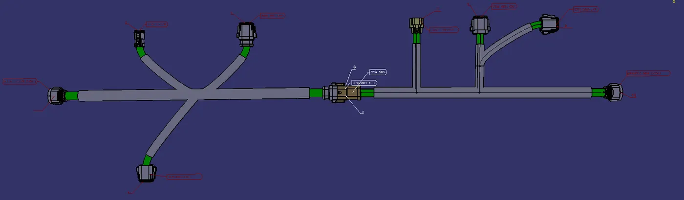
12.Then Apply Protection covering to Multi-Branchable. (Corrugated Tubes)
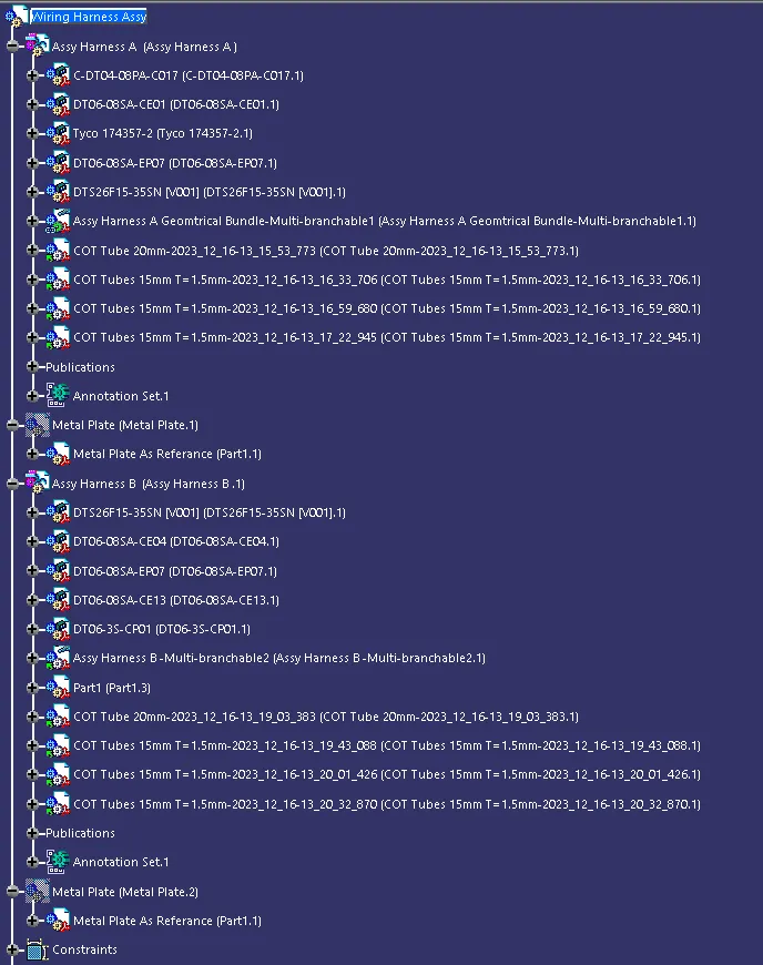
Tree Structure:
Routing Requirements:
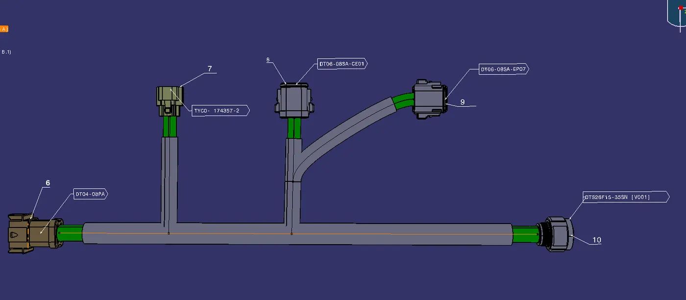
Harness-A:
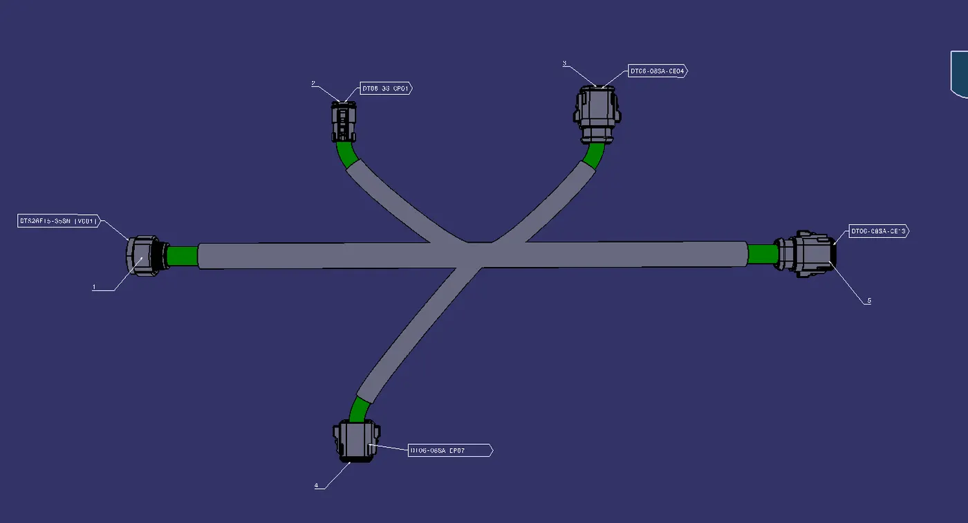
Harness-B:
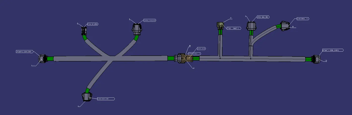
Wiring Harness Assembly:
Cat.Part Has Been generated for the Whole Assembly And Attached as Zip file.
Then Cat.part has been converted as .igs format And attached as Zip File.