Wiring harness design in CATIA V5 - 3D modeling Week 5 & 6 Challenge
Q1. Route the following harness layout in Electrical workbench. Make assumption for harness bundle diameters. Use the connectors provided. After completion of routing,
- Check the bundle Continuity. Add snap of result in submission
- Add annotation to all connectors. Make an assumptions for annotations like connect 1 , 2 etc
- Check for the bundle warning. Add snap.
- Generate CAT.part of harness assembly and convert is in. igs format.
First of all we'll download all the Cat parts and will create Point and Axis system for each part .
then all the parts will be defined as Connector and then later onwards a Connector connection point is created for the Connection joint.
A bundle Connection Point is also created on all the Parts.
Once the All the parts are electrically defined then the sketch is created as per the connector location in the image.
Here 5 and 6 Connector will be connected later . so the Harness B connection is made separately and Harness A separately.
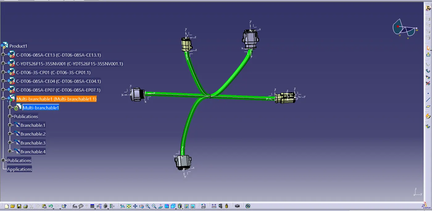
Multi Branchable wiring Harness is carried out using branch point for the connector as per the diagram.
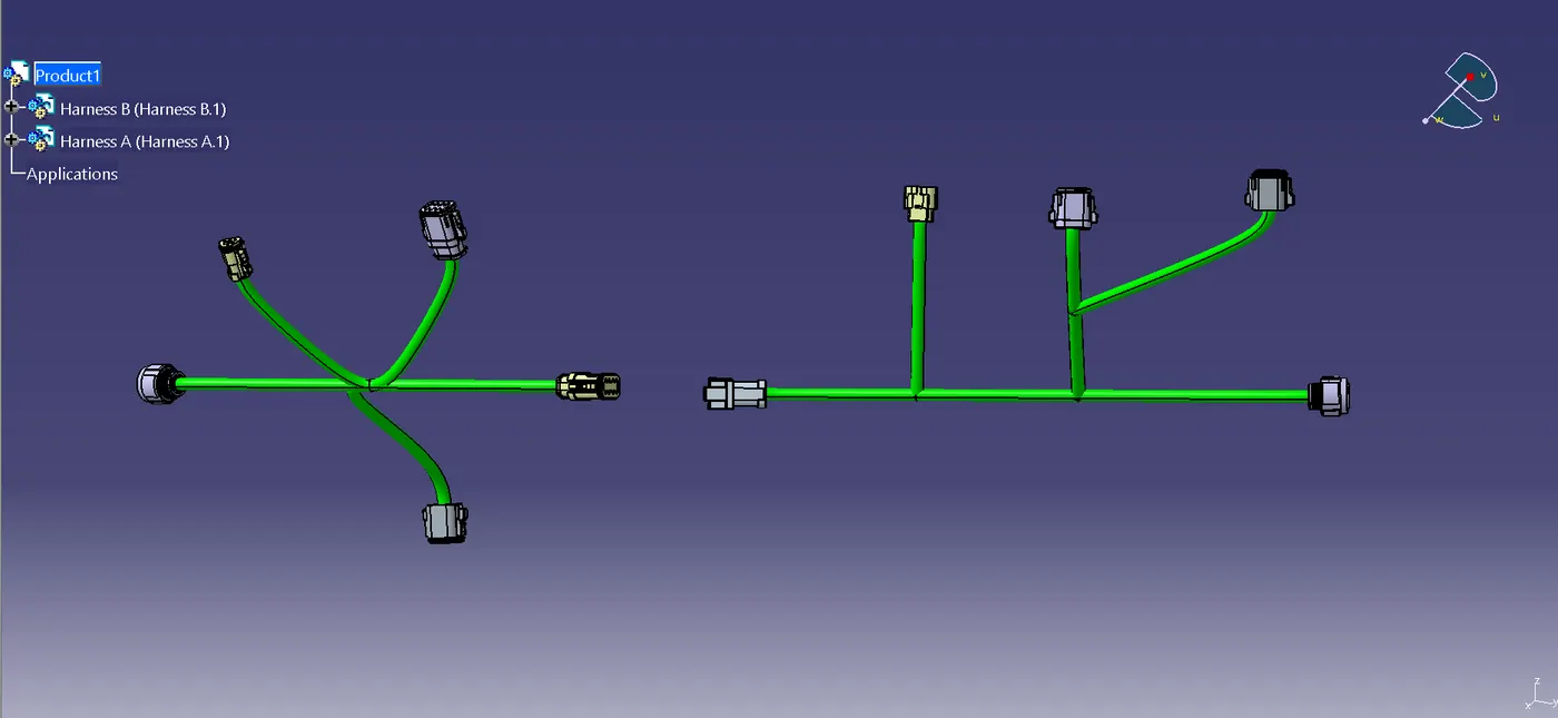
In this way both the Wiring parts have been created with wiring routing and Harness and then both the 5 and 6 connector will connect using link connector command.
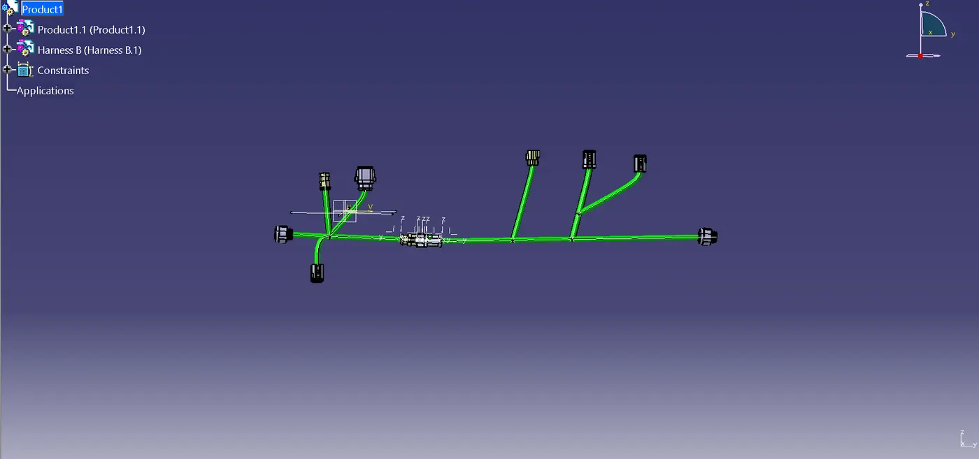 *Check the bundle Continuity. Add snap of result in submission
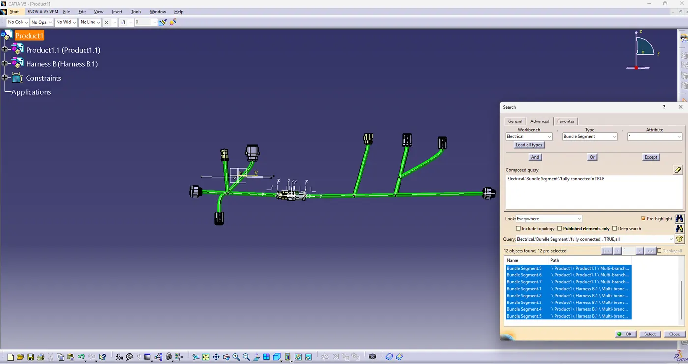
To check the Bundle Continuity , we've to proceed with the search box where workbench is selected as electrical and type as Bundle Segment with attribute as Fully Connected .
The following Bundle Segment is showing that the Bundle continuity is true and is connected.
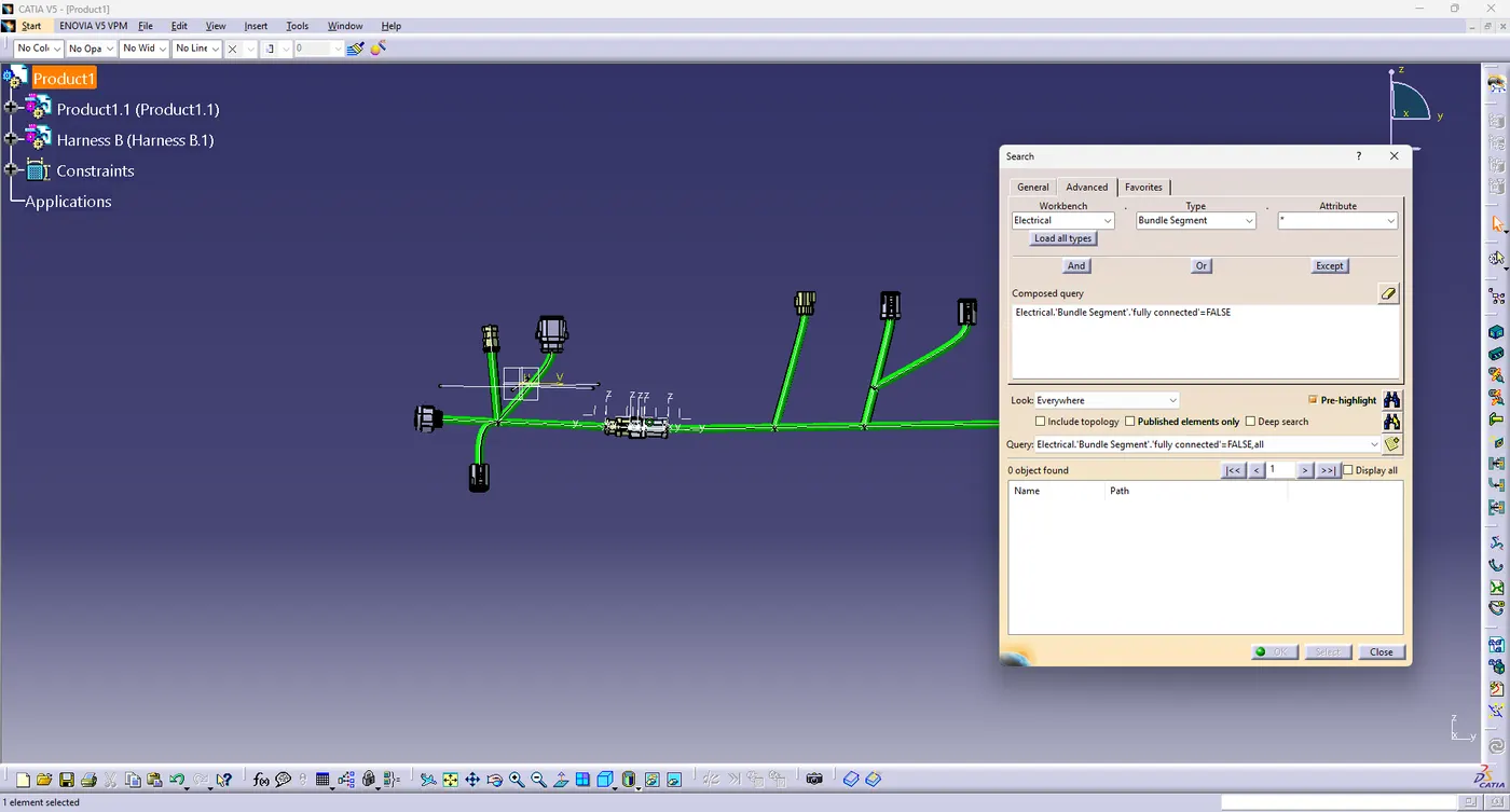
Here Similarly check for the False but no results found which shows the Bundle is correctly Connected.
* Add annotation to all connectors. Make an assumptions for annotations like connect 1 , 2 etc
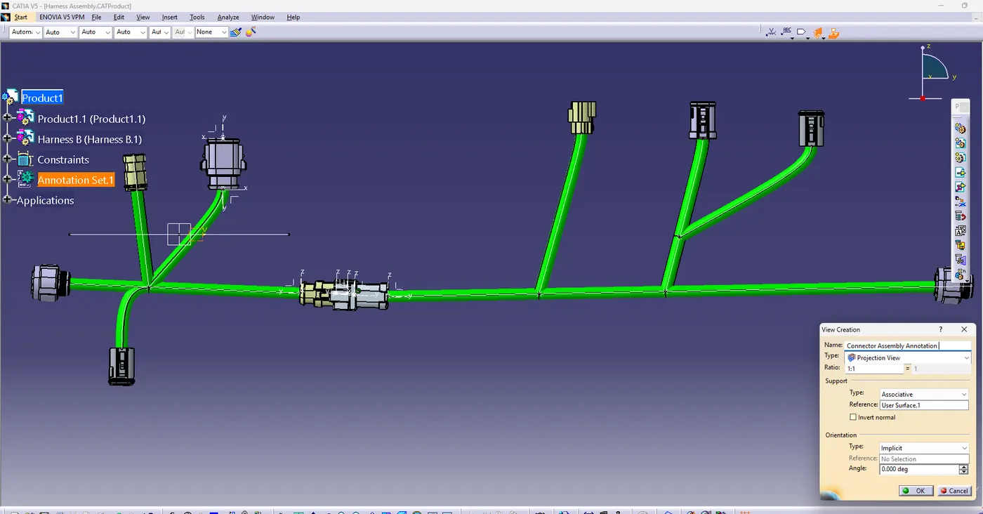
To create an annotation A Reference plane is created where the annotation will lie.
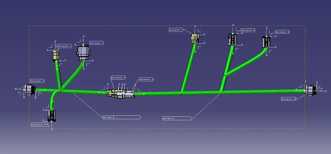
By using Flat with Leader command as many Annotation Can be Created .
*Generate CAT.part of harness assembly and convert is in. igs format.
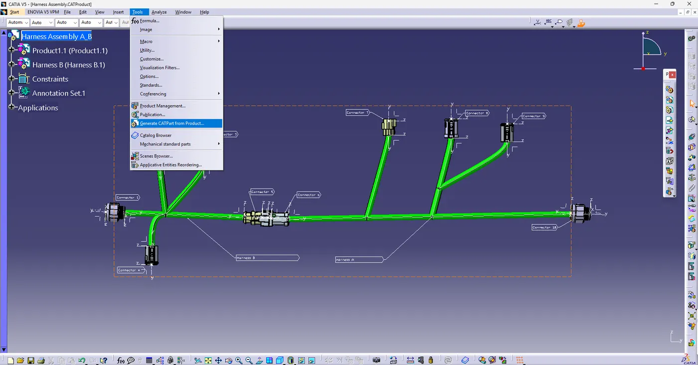
Through generate CAT part from product in the tools section CATpart can be created in any format .
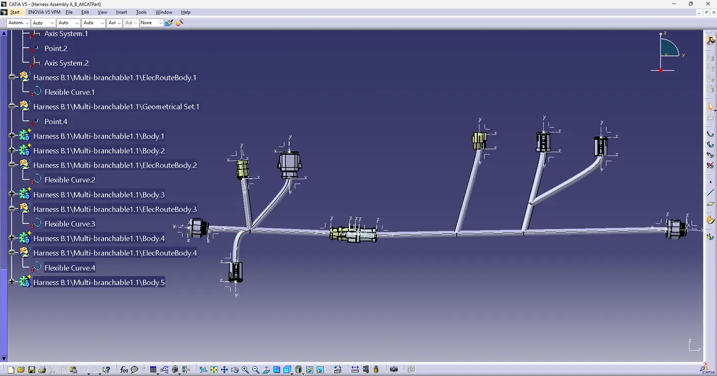
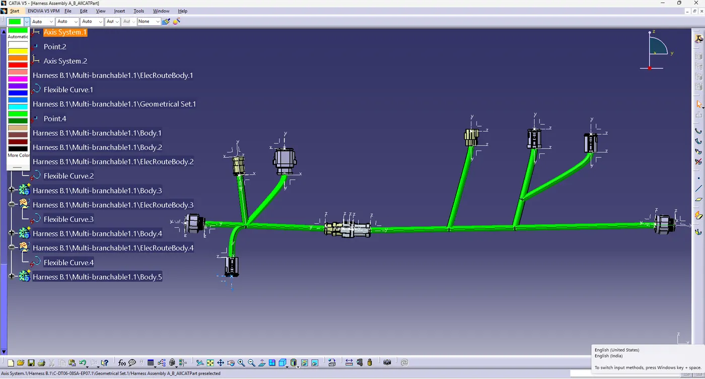
Once the CATPart is created its visible in grey color one can change the color of wiring back to green for the representation.
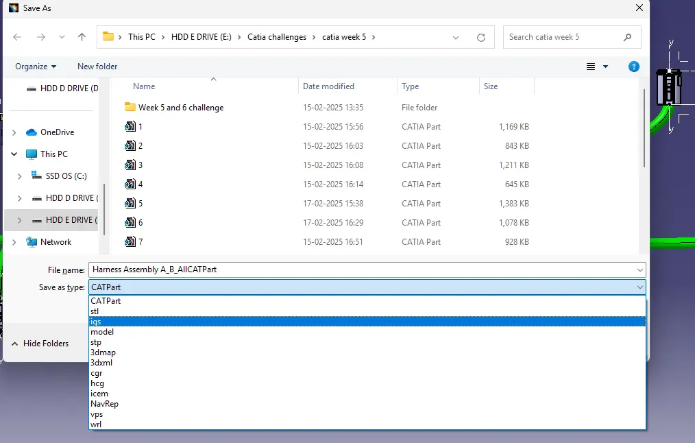
Last the file is saved as igs part for the further usage in any Designing software such as solidwork, catia or ansys.