Wiring harness design in CATIA V5 - 3D modeling Week 5 & 6 Challenge
WIRE HARNESS DESIGN
Harness A :
Define a Connector
1. Open or Create the Connector Part
1. Create the Geometry:
o Use the Part Design or Generative Shape Design workbench to create the connector's 3D geometry.
2. Import an Existing Connector Model:
o If the connector is pre-designed, import the CAD file into CATIA.
2. Switch to the Electrical Part Design Workbench
- Go to Start > Equipment & Systems > Electrical Part Design.
3. Define the Connector
1. Access the Define Connector Tool:
o In the toolbar, select Define Connector.
2. Assign Basic Properties:
o Click the connector geometry to define it as an electrical connector.
o Enter a name and description for identification.
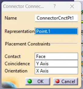
4. Define Connection Points
1. Add Connector Connection Points:
o Select Define Connector Connection Point from the toolbar.
o Click on the face or surface of the pin or interface where the connector will mate.
o Specify:
§ Direction: Set the orientation of the connection point.
§ Type: Define the connection type (e.g., male, female).
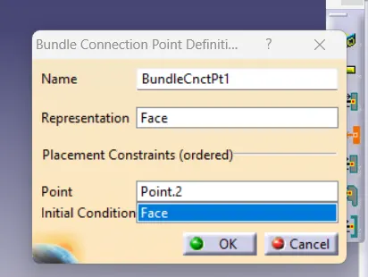
2. Define Bundle Connection Points:
o Select Define Bundle Connection Point.
o Click on the surface or edge where the wiring bundle enters the connector.
o Set parameters such as:
§ Diameter: Define the maximum allowable bundle diameter.
§ Direction: Ensure it aligns with the intended wire routing.
5. Validate the Definition
1. Check All Defined Points:
o Ensure all connection points are correctly placed and oriented.
2. Save the Defined Connector:
o Save the part with all electrical definitions.
CREATE A BUNDLE :
1. Prepare Your Assembly
1. Insert Components:
o Use the Electrical Harness Assembly workbench to add components like connectors, clamps, and supports into your assembly.
2. Ensure Definitions:
o Components like connectors should already have their bundle connection points defined in the Electrical Part Design workbench.
2. Switch to the Electrical Harness Installation Workbench
- Go to Start > Equipment & Systems > Electrical Harness Installation.
3. Create a Bundle Segment
1. Open the Bundle Segment Tool:
o Click the Bundle Segment tool in the toolbar.
2. Define Bundle Points:
o Click on the bundle connection points of the connectors or supports to define the routing path of the bundle.
3. Set Bundle Parameters:
o In the dialog box, specify:
§ Diameter: Define the diameter of the bundle.
§ Bend Radius: Ensure the radius meets design constraints to avoid sharp bends.
§ Material: Select the insulation material for the bundle.
4. Draw the Path:
o Use geometry (lines, curves, or edges) or manually define points to create the bundle's routing.
4. Add Branch Points
1. Insert Branch Points:
o Use the Branch Point tool to split or merge bundle segments at specific locations.
o Define additional bundle paths originating from the branch point.
2. Route Additional Segments:
o Create new bundle segments from the branch point to connect other components.
5. Validate the Bundle
1. Analyze Continuity:
o Use the Connectivity Analysis tool to ensure all components are properly connected by the bundle.
2. Check Bend Radius:
o Verify that the bundle adheres to the specified minimum bend radius.
3. Inspect Geometry:
o Ensure the bundle does not interfere with other components in the assembly.
6. Save the Assembly
- Save the harness assembly and associated bundle data for future use or modifications.
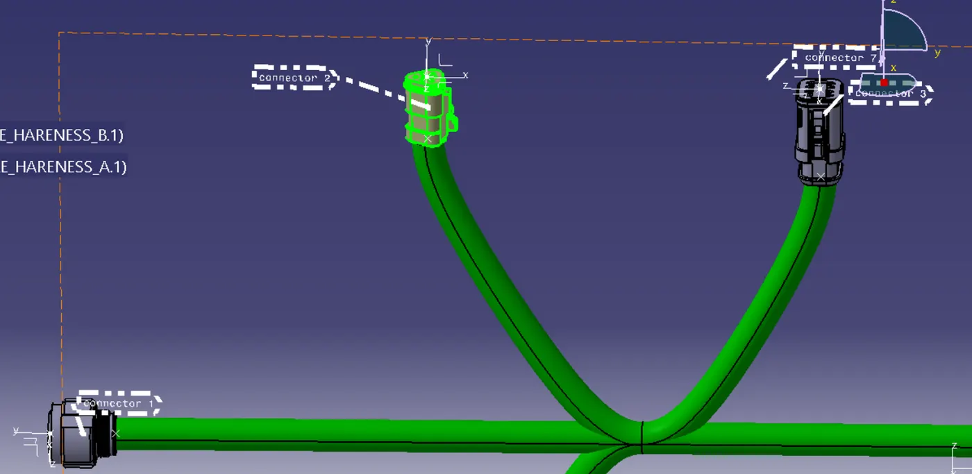
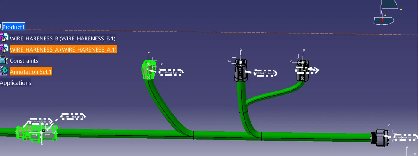
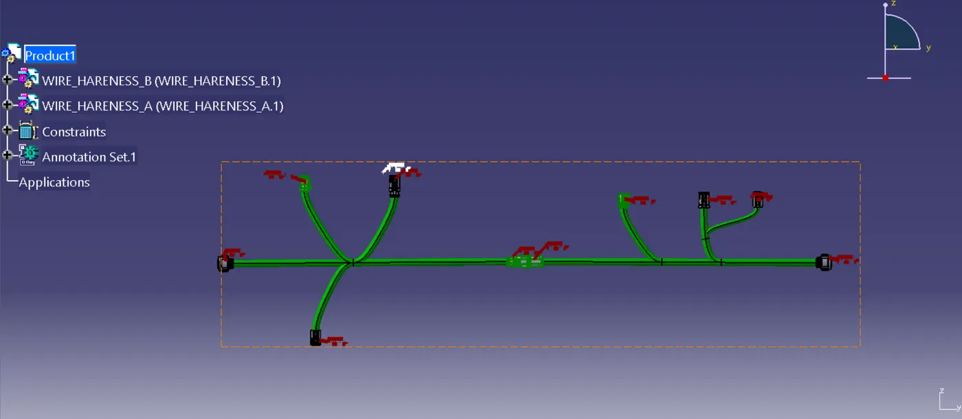
Thus for create a HARNESS B with given connector and create a bundle .
And connect harness A and B and check their connectivity.
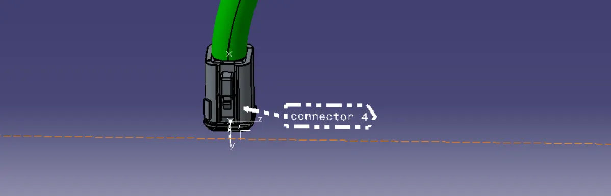
and give annotation to the connectors.
DESIGN VIEWS: