Wiring harness design in CATIA V5 - 3D modeling Week 5 & 6 Challenge
REPORT:
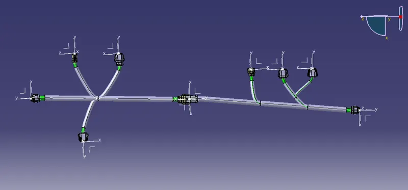
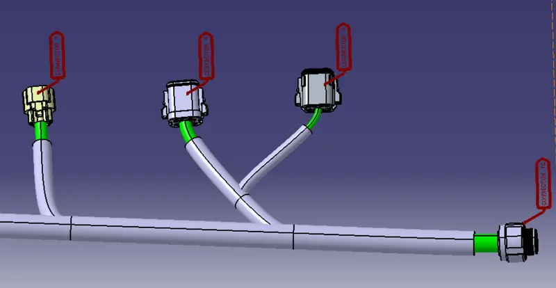
Rout the harness a and harness b. for the routing of two harness first downloaded the required connectors from te.com website. the connectors are converted into catpart using catia v5. after that the connectors are checked for the compaptibility. and the connectors are opened in the part workbench for giving the required parameters. after giving the parameters to cnnectors. these connectors are opened in electrical workbench, and the connectors are defined electically. and defined the connector connection point and bundle connection point. after defining every connectors the required connectors for harness A is added to a new product file. and connectors for the harness B in another product file. the connectors are seperated for the routing process using manipulation tools in assembly workbench. after that the created product is converted into electrical from electrical assembly workbench. and created a multibranchable to connector 6 to connector 10,which is the main branch. after that created branch points for the sub braches to connect the other connectors. the sub branches are created using multibranchable option. by giving required dia and slag. the same procedure is used for creating routing for the harness B. after that created a new product file and added harness A and harness B in it. both the harness are checked for the connection continuity seperately.after that the protection cover were given for both harnessess. after that the two harness were connected ussing electrical assembly workbench.after that the product file is converted to catpart.by using the comand generate catpart from product. required pictures are given below
harness A
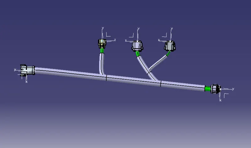
harness B
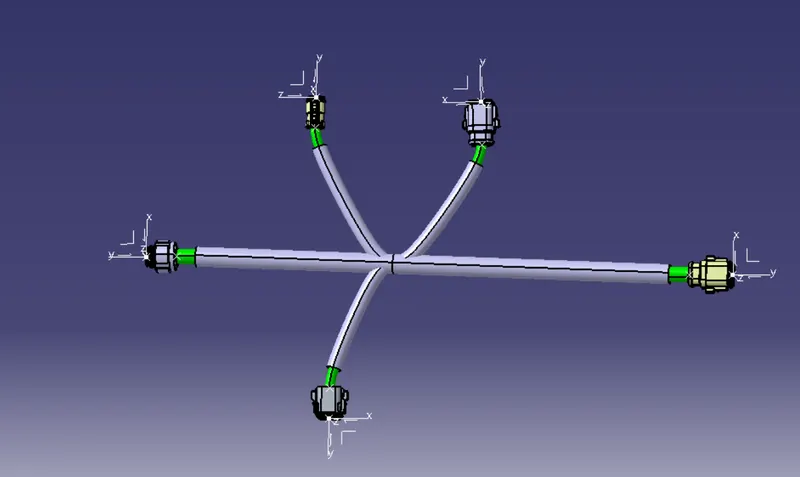
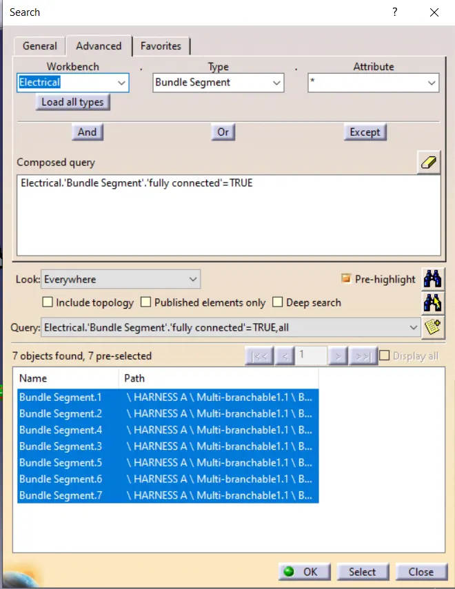
connection continuity
harness A
condition:FALSE
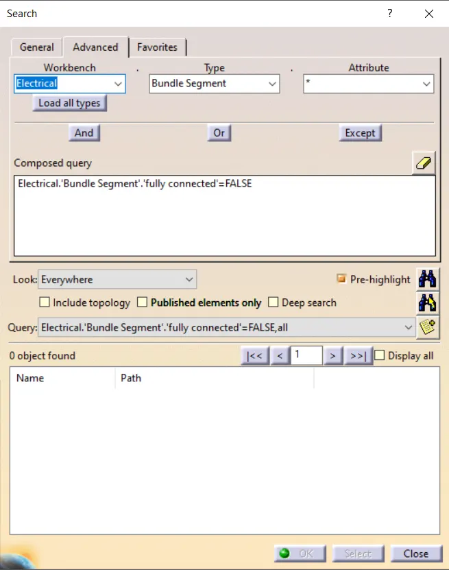
CONDITION:TRUE
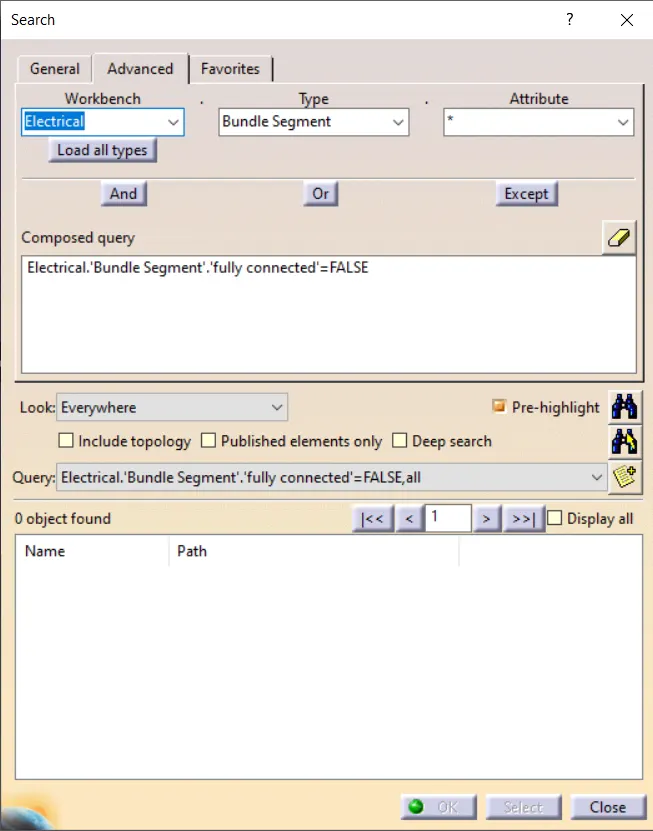
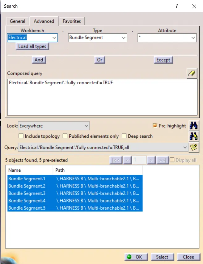
HARNESS B
CONDITION: FALSE
CONDITION:TRUE
BUNDLE WARNING
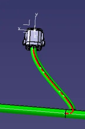
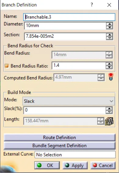
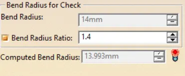
the bundle warning is shown in the red colour ,which means here the required bend radiues is 14mm ,due to the tangent direction the bend radius is less than the required . the error was corrected by changing the tangent direction.after that the error was corrected and warning signel became green.the pictures are given below
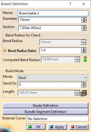
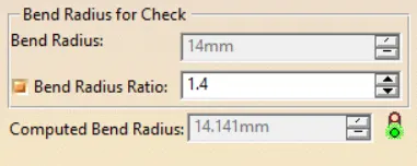
anotations:
FINAL ASSEMBLY