Wiring harness design in CATIA V5 - 3D modeling Week 5 & 6 Challenge
As per the challenge question, i have made the wiring harness assembly. The required connectors has downloded from the te.com.
For proper placing of the connector i have used positioned sketch and a base plate to keep the all connectors in a same plane.
Connector placement,
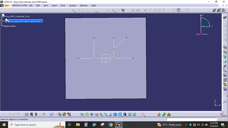
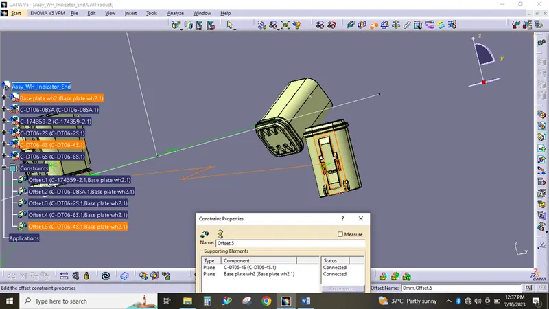
Offset constraints were used to keep the connectors in the same plane. After placing the constraints has deleted.
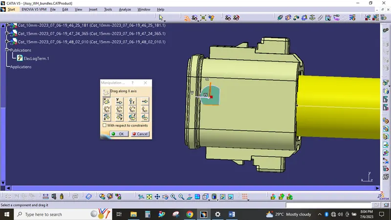
For placing - manipulation and smart move, compass used,
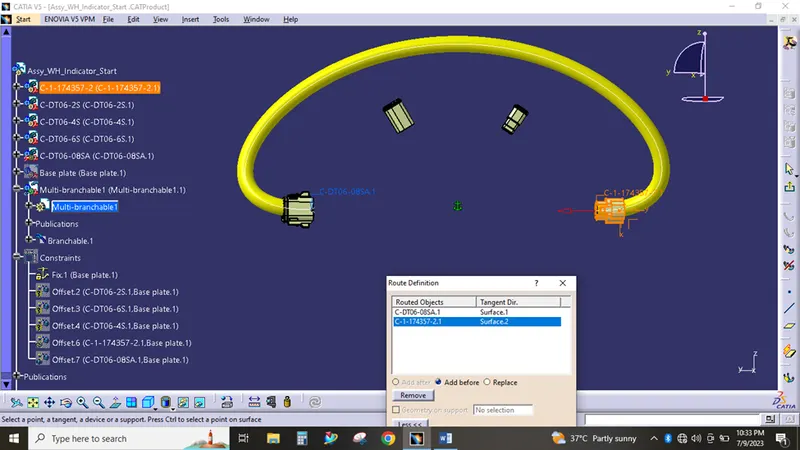
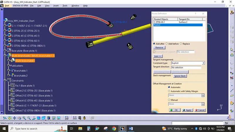
WH bundle creation using multi-branchable command,
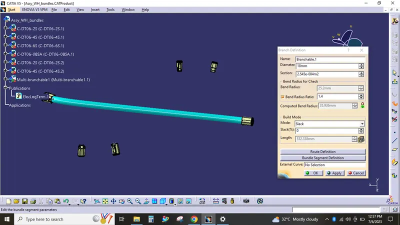
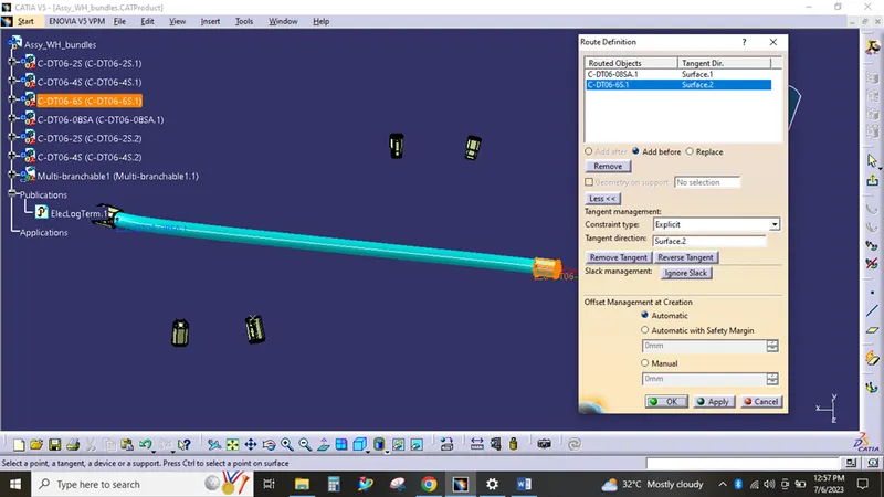
Route definition,
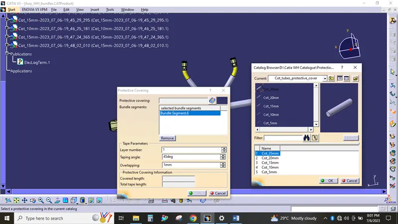
Protection covering,
As per the assumed diameter of bundle, the desired protective cover (COT TUBES) has provided from the catalogue,
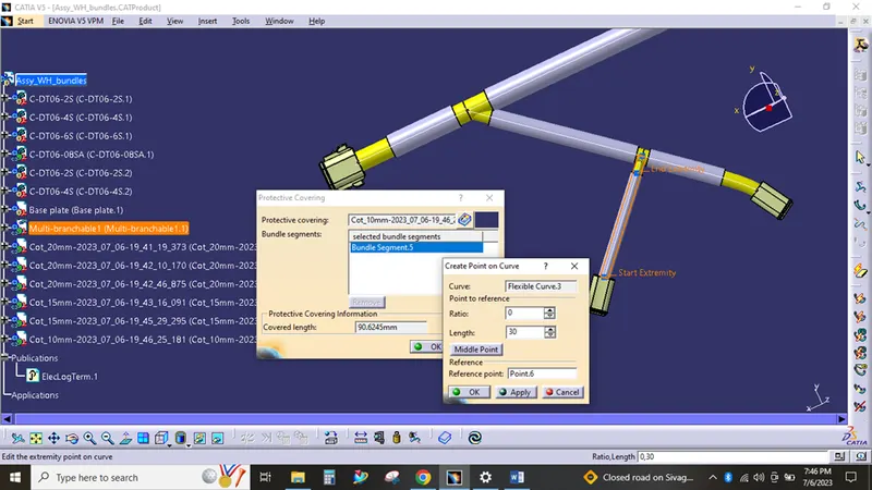
From connector point - 30 mm gap provided for covering
Bundle error snaps,
The most of the bundle error has cleared by "reverse tangent" option.
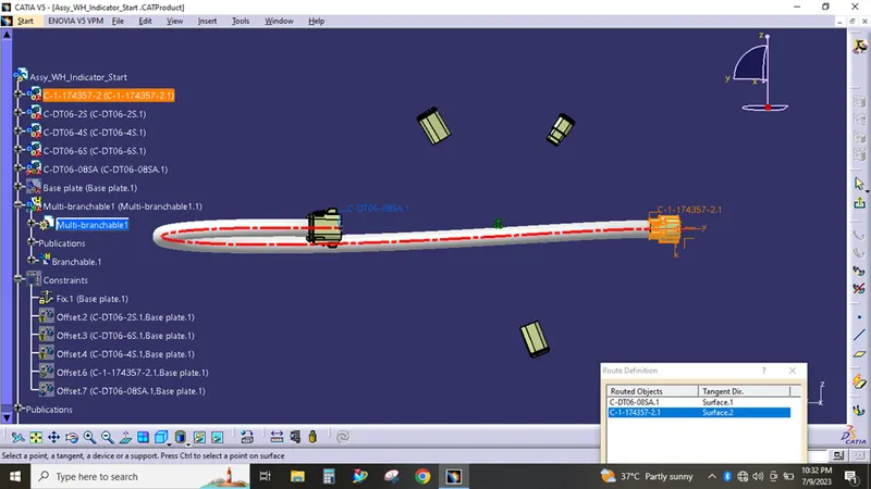
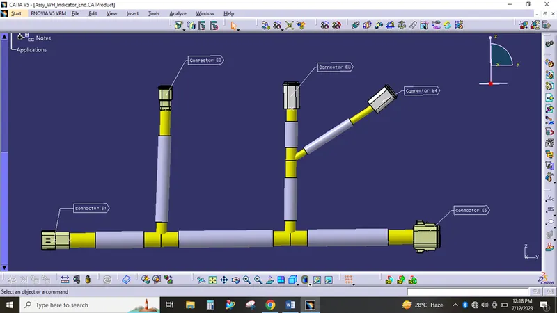
Harness A = Assy_WH_Indicator_End
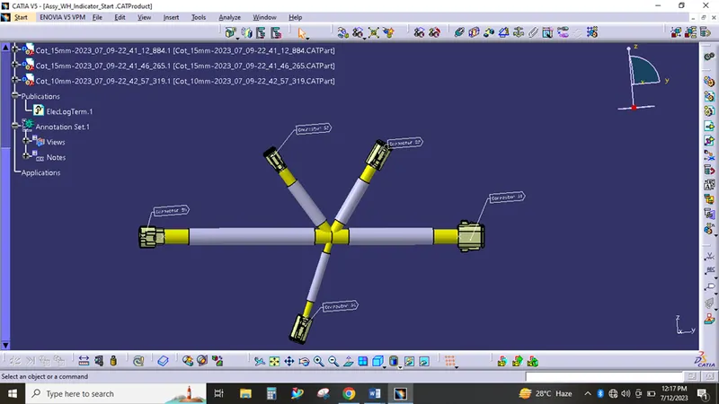
Harness B = Assy_WH_Indicator_Start
Bundle continuity checking,
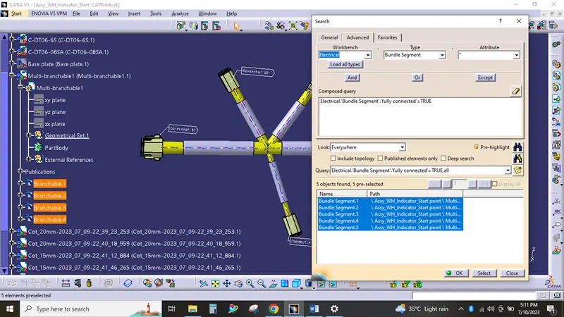
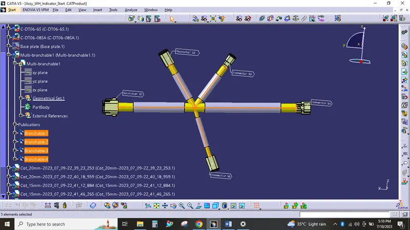
Harness A - Continuity error found
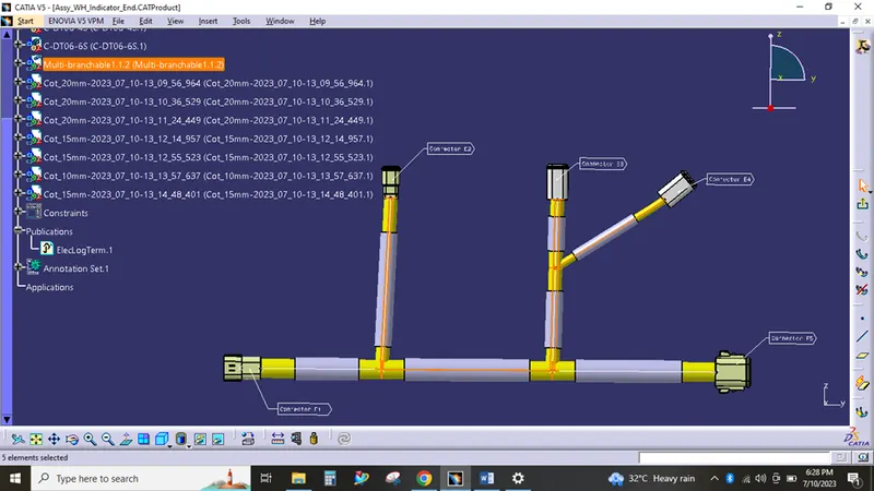
The continuity can be recovered by changing the branchig points and i have re-routed the bungles where the continuity get disconnected
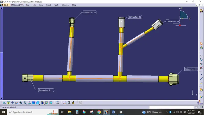
Harness A & B continuity
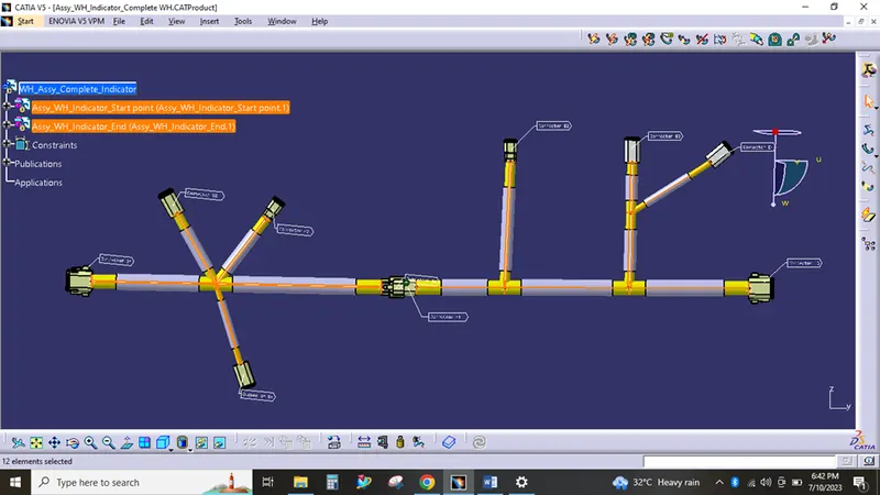
Annotation creation,
Creation of view plane as front plane ( one side of connector face )
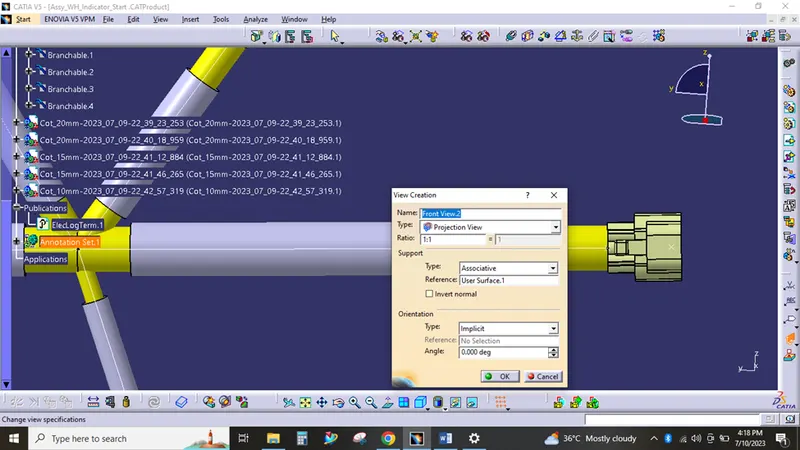
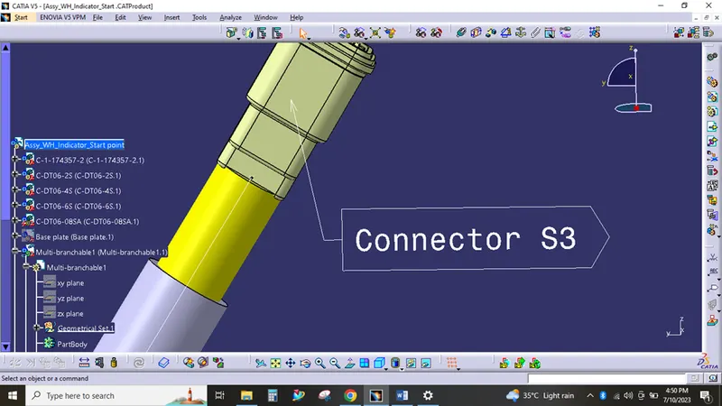
Naming the connector,
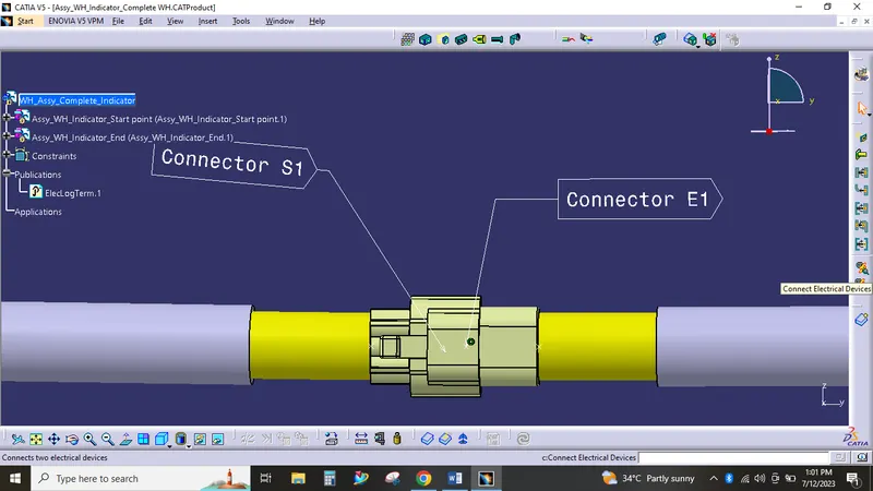
Harness A and B interconnection,
In the electrical assembly design workbench, The command connect electrical devices is used to make interconnections between harness A and B.
Final Assembly,
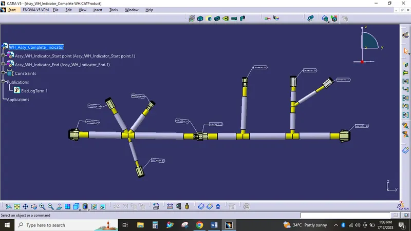
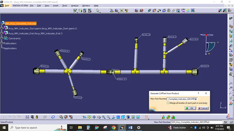
CATpart generation,
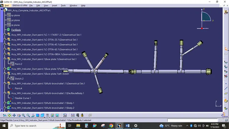
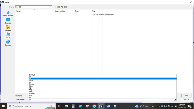
Converting to IGES file,
All the part files, catalogues and assembly files has attached as a single zip file in the attachment section.