Wiring harness design in CATIA V5 - 3D modeling Week 5 & 6 Challenge
Wiring harness design in CATIA V5 - 3D modeling Week 5 & 6 Challenge
Objective: Route the following harness layout in the Electrical workbench. Make an assumption for harness bundle diameters. Use the connectors provided. After completion of routing.
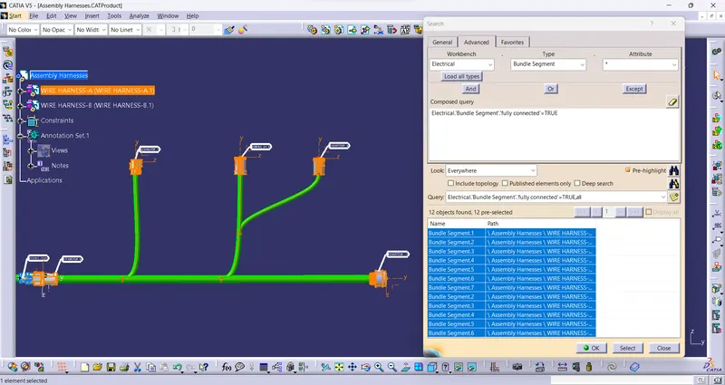
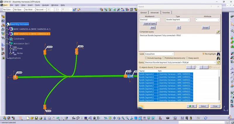
- Check the bundle Continuity. Add a snap of the result in the submission
- Add annotation to all connectors. Make assumptions for annotations like connect 1, 2, etc
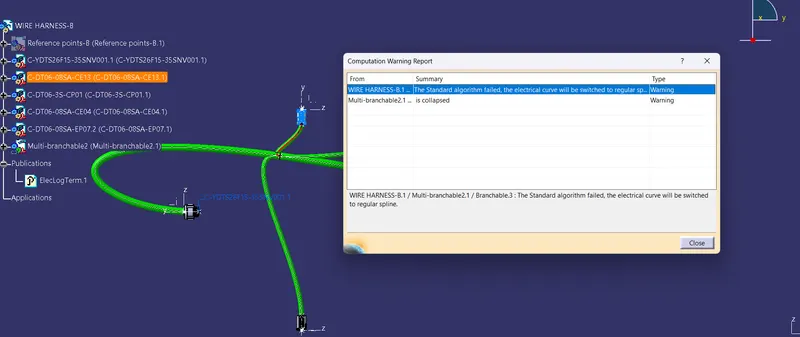
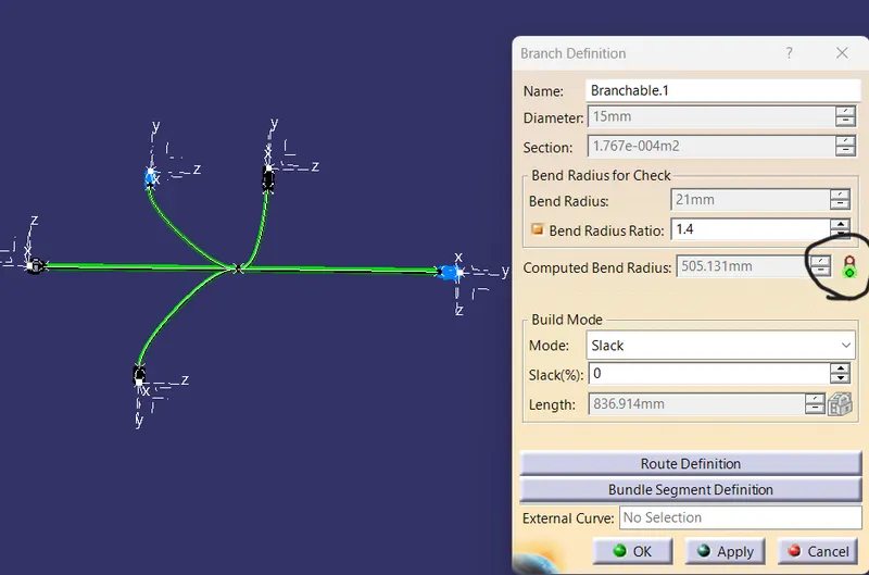
- Check for the bundle warning. Add snap.
- Generate CAT.part of harness assembly and convert it in. igs format.
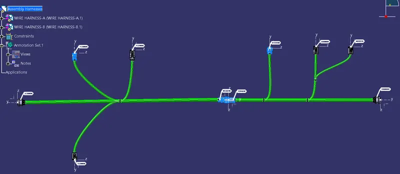
Given the layout of Harnesses A & B:
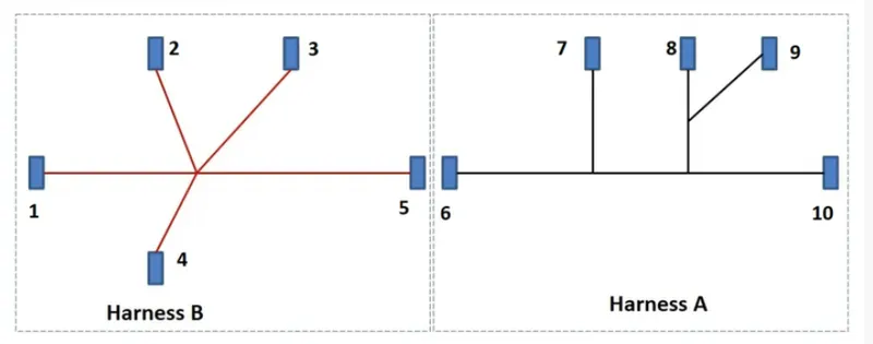
Defining Electrical parameters to All Connectors:
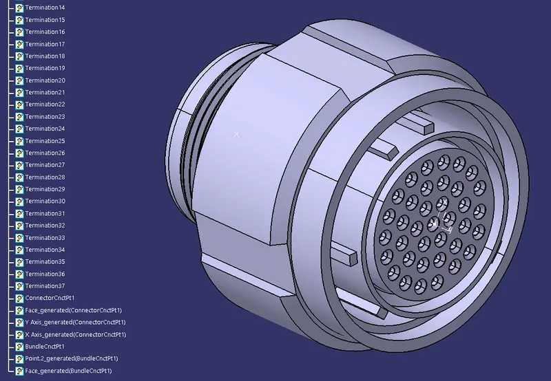
Connectirs definition for Connectors:
- Create/Download connector 3D
- Create required Geometrical parameters.
- Defining part as connector
- Define connector connection point
- Define Bundle connection point
- If require Define cavity connection point.
These electrical parameters to be defined, connectors converted into electrical components.
The above reference figure various connectors mentioned below.
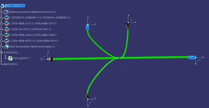
Harness-B
1. C-YDTS26F15-35SNV001
2. C-DT06-3S-CP01
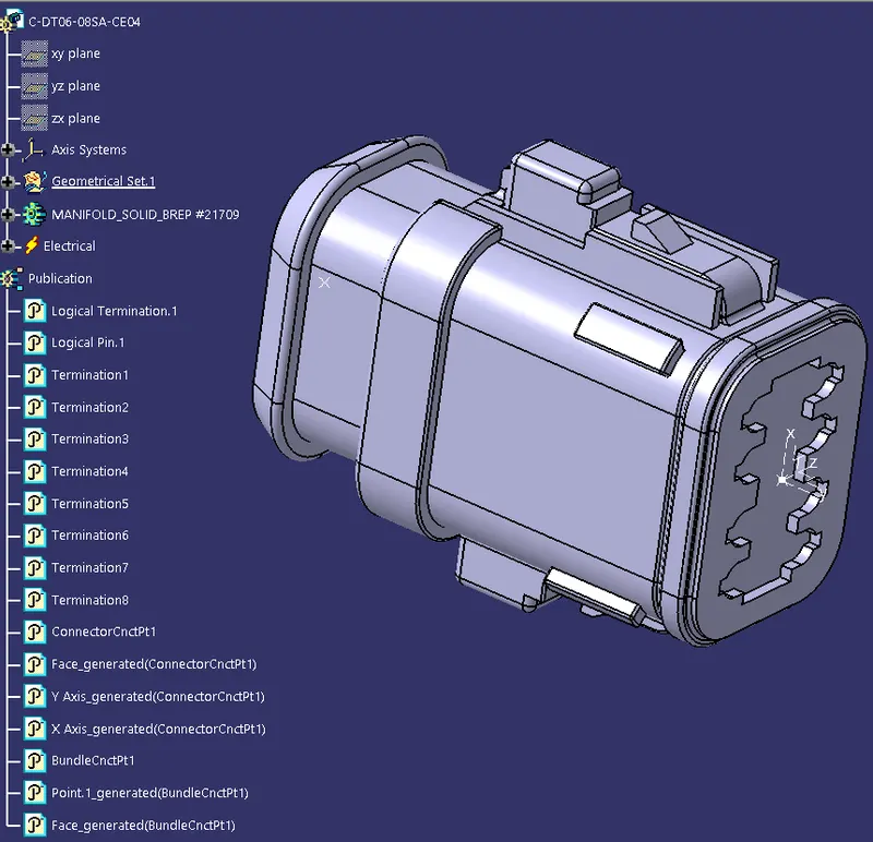
3. C-DT06-08SA-CE04
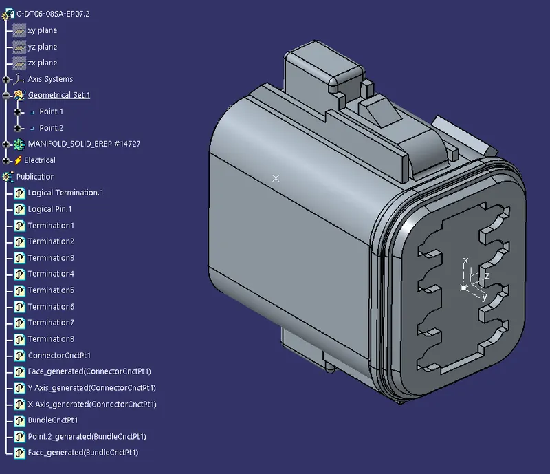
4. C-DT06-08SA-EP07
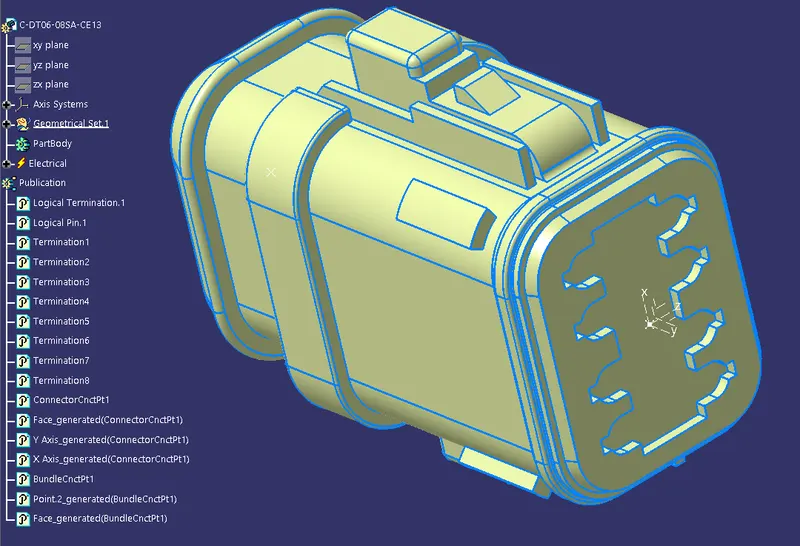
5. C-DT06-08SA-CE13
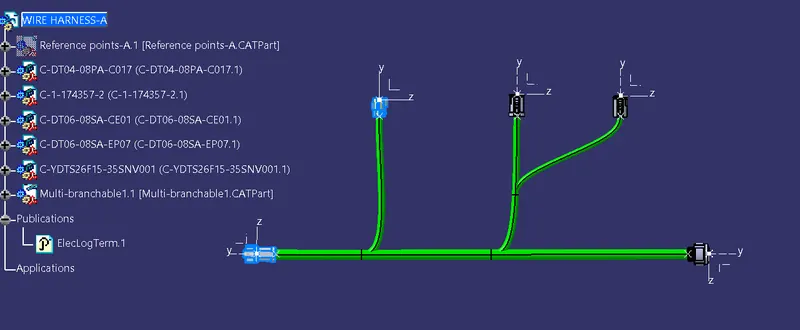
Harness-A
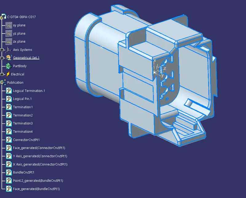
6. C-DT04-08PA-C017
7. C-1-174357-2
8. C-DT06-08SA-CE01
9. C-DT06-08SA-EP07
10. C-YDTS26F15-35SNV001
Harness-B:
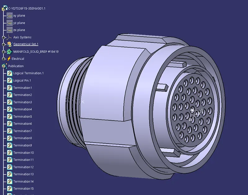
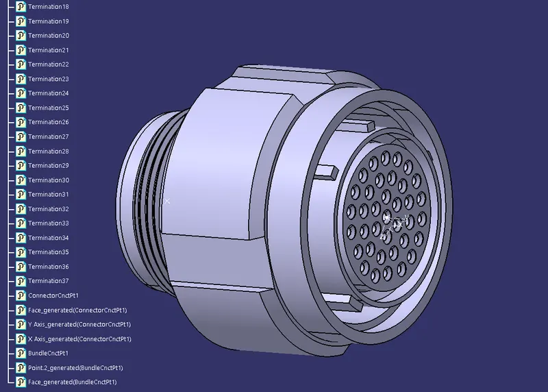
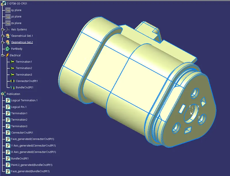
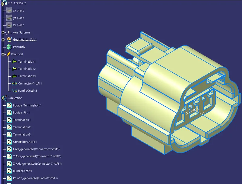
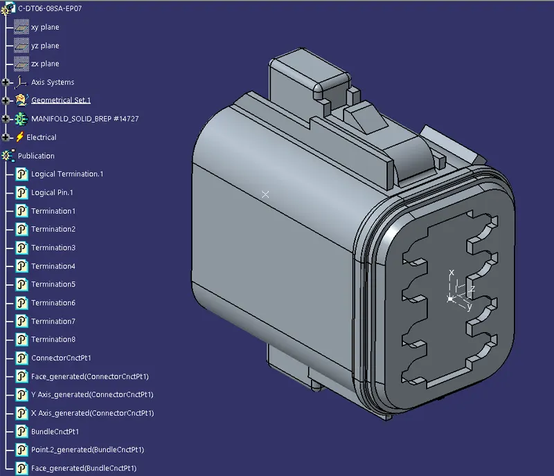
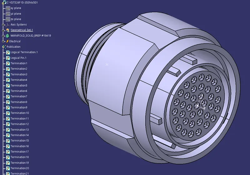
find the below connectors with defined electrical parameters in CATIA V5
1. C-YDTS26F15-35SNV001
2. C-DT06-3S-CP01
3. C-DT06-08SA-CE04
4. C-DT06-08SA-EP07
5. C-DT06-08SA-CE13
Harness-A:
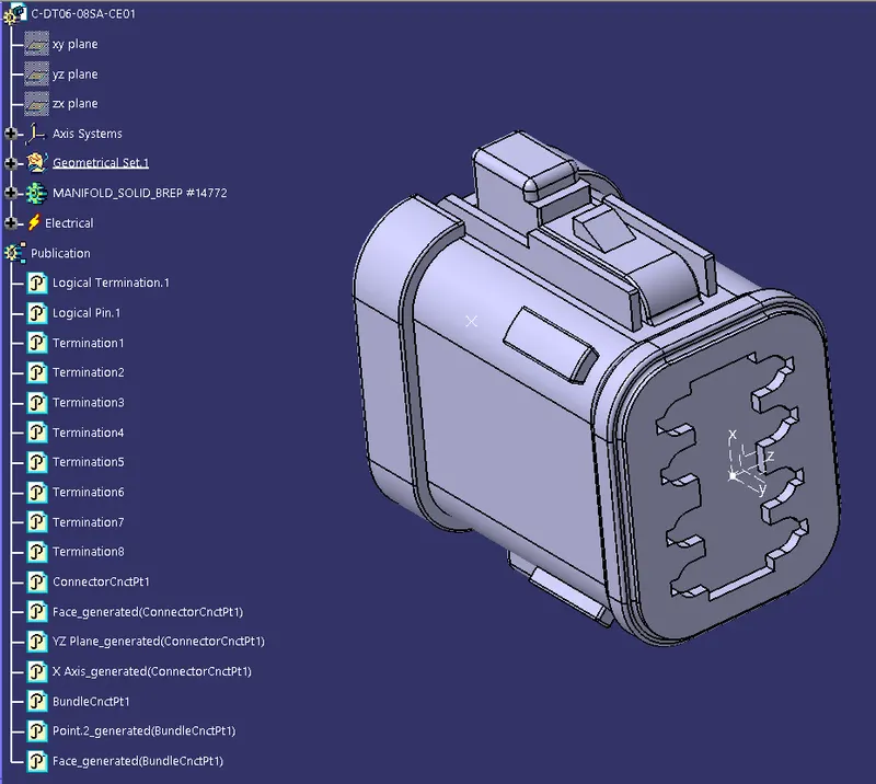
find the below connectors with defined electrical parameters in CATIA V5
6. C-DT04-08PA-C017
7. C-1-174357-2
8. C-DT06-08SA-CE01
9. C-DT06-08SA-EP07
10. C-YDTS26F15-35SNV001
Assembly Harness-A:
Assembly Harness-B:
Wire Harness Assembly A and B:
Important Design parameters keep remembering in the Harness design in CATIA V5:
*Bundle Continuity:
In the harness bundle continuity will be checked in the CATIA V5 smart feature in the Edit at the top Toolbar, next click on edit shown search option in the command will be selected as electrical>bundle segment>fully connected>ok, it will be shown like continuity true means connected bundle segments and false means its discontinuity bundle segment, whatever requirement we can select find the result in the search bundle continuity procedures.
* Bundle Warnings:
Bundle warnings are shown in the symbol of the yellow exclamatory mark "!".
Bundle warnings are shown bundle definition command also will be shown in red color and its good for designing green color visible.
*Generated CAT.part of harness assembly and convert into the part file:
These assembled product files are converted into a part file in CATIA V5 is mostly used for other software also these part used to open part designing of requirements.
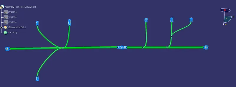
Conclusion:
Hence, Finally Harnesses Routed the following harness layout in the Electrical workbench and assumed for harness bundle diameters. Various connectors provided and these defined as electrical connectors.
After the completion of routing.
- Checked the bundle Continuity. Added a snap of the result in the submission
- Added annotation to all connectors. Made assumptions for annotations like connect 1, 2, etc
- Checked for the bundle warning. Added snap.
- Generated CAT.part of harness assembly and converted it in. igs format.