Wiring harness design in CATIA V5 - 3D modeling Week 5 & 6 Challenge
Wiring harness design in CATIA V5 - 3D modelling Week 5 & 6 Challenge
AIM
Create two electrical harnesses using the given layout and interconnect them as a single harness assembly, check the bundle continuity, bundle warnings and give annotations to the harness assembly.
INTRODUCTION
Automotive Wiring Harness Parts
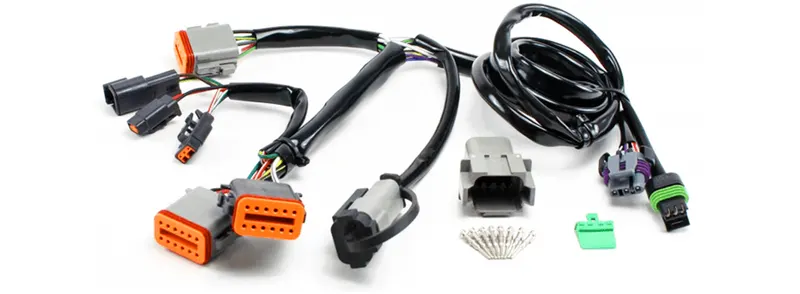
Wiring Harnesses and Connectors are part of the wiring systems in your vehicle. A harness is a group of cables or wires that are secured together by proofing material like cable sleeves, lacing, conduit or straps. Wire harnesses have the advantage over loose cables in that they conserve space and provide a strong resistance to vibrations and abrasions in the vehicle. Wire-harnesses also remove any confusion or possible incorrect installation by grouping the wires into a single connection device.
Connectors attach to or pass the wires through a component. They are water and heat resistant. A hard outer shell with a locking clip holds two halves of a connector together. The pins and sockets are crimped to the wire both at the insulation and the bare wire. They are made so that they fit together perfectly, but can also be easily disconnected when needed. A rubber seal encloses all the wires and keeps the wires protected from moisture and other abrasive conditions.
Both harnesses and connectors in your vehicle should be checked periodically for damage or breakage. If any of the electrical components being to work erratically or if you keep tripping up your fuse even when it is replaced, it is an indication that there is a fault in the harnesses or connectors. At Buy Auto Parts we stock a wide variety of wiring harnesses and connectors for every car make and model.
The key components of a wiring harness include
- Connectors
- Terminations
- Locks
- Wires
- Cables
- External coverings.
OBJECTIVE
- Download the mechanical components from the given source and define them as electrical parts using the electrical part design workbench.
- Using the given reference layout, arrange the required connectors to their appropriate places and create harness A and Harness B.
- Using electrical harness assembly workbench, interconnect the Harness A and Harness B.
- Give annotations on each component in the final harness assembly.
DESIGN METHODOLOGY
STEP-1
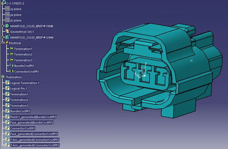
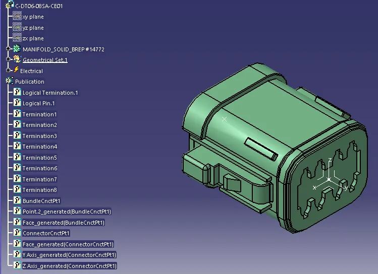
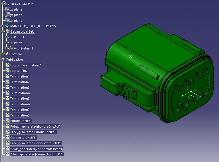
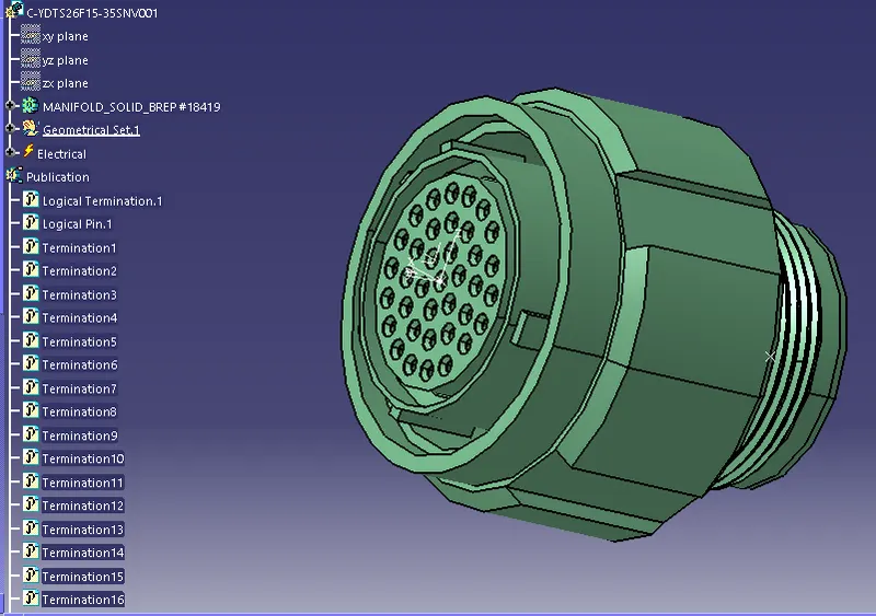
Defining mechanical connectors electrically.
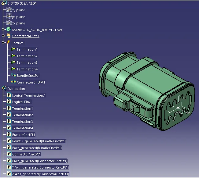
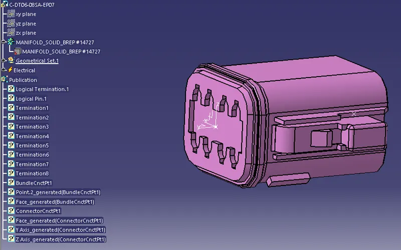
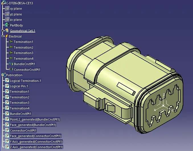
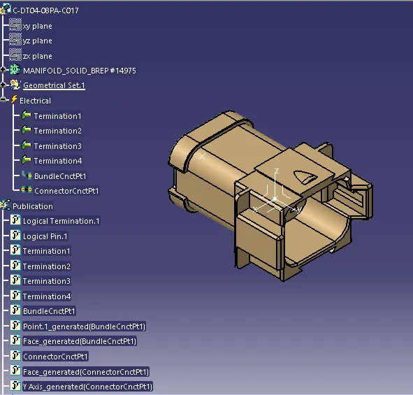
Download the required Connectors from the source and convert the mechanical connectors electrically by using the electrical part design work bench by following below steps.
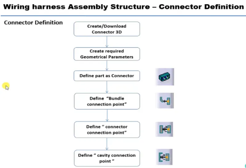
- First download the connectors and mounting clip from the given link source.
- Get into the mechanical part workbench to create required geometrical parameters. Create connector connection point and bundle connection point on the required sides of the CAD part.
- Create axis system on the connector connection point such a way that the Y coordinate facing normal to the connector face, X coordinate facing towards the locking mechanism and Z coordinate facing to the top.
- Create cavity connection point for connectors having the cavity for mounting clips
Using the geometrical parameters created,
- Define part as electrical connector.
- Define bundle connection point.
- Define connector connection point.
- Define cavity connection point.
DESIGN METHODOLOGY
STEP-1:
HARDNESS A
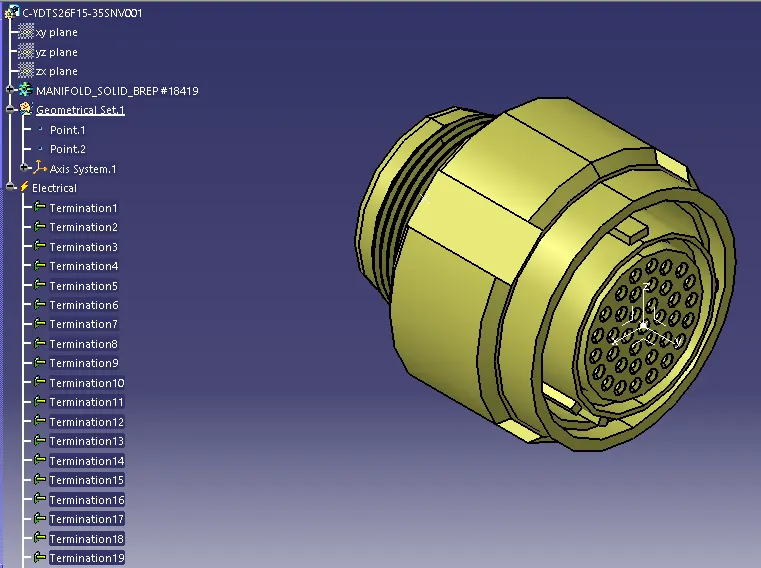
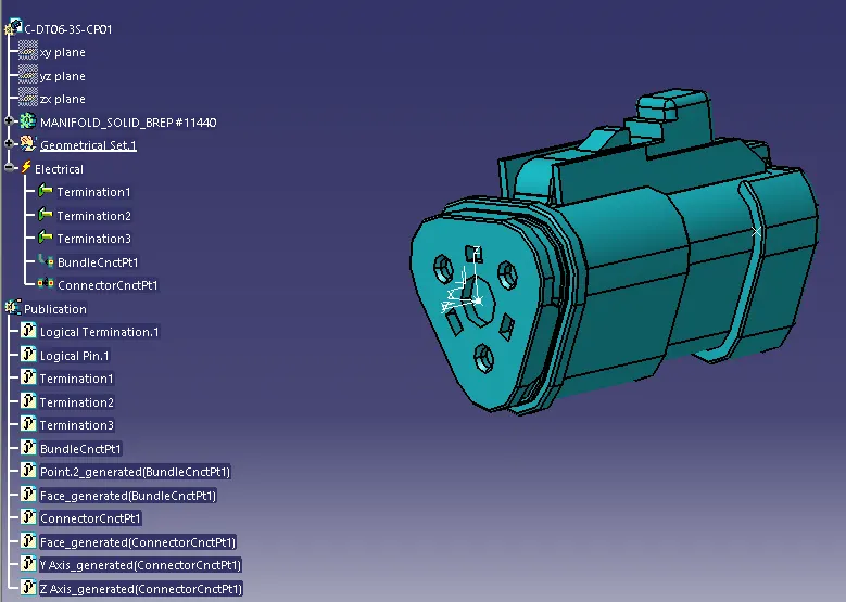
HARDNESS A:
STEP-2
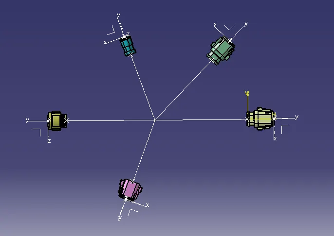
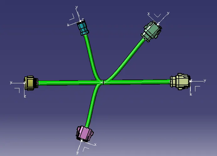
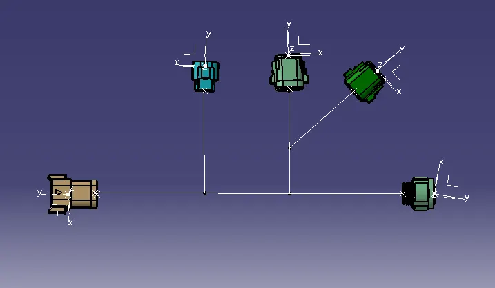
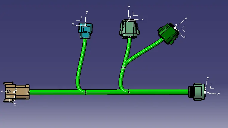
Create harness A and harness B as shown below by using the electrical harness workbench in CATIA V5.
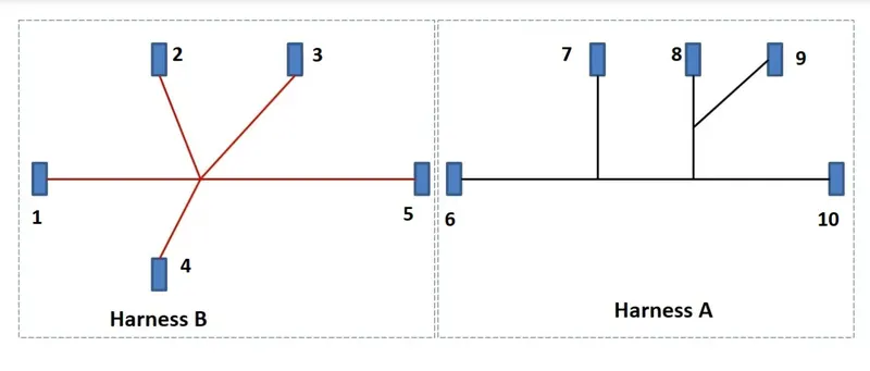
Procedure for creating the harness
- Create a product fine and define it electrically using Geometrical Bundle option
- Create a reference drawing part for proper alignment of connectors.
- Using Snap, move and compass place the connectors at desired locations
- Bundle segments are created with connectors bundle connection points. (Bundle diameters are assumed as 10mm and 5mm)
- Create branch point on the main multi branchable bundle.
- Create sub multi branchable segments.
HARNESS B
HARDNESS A:
STEP3
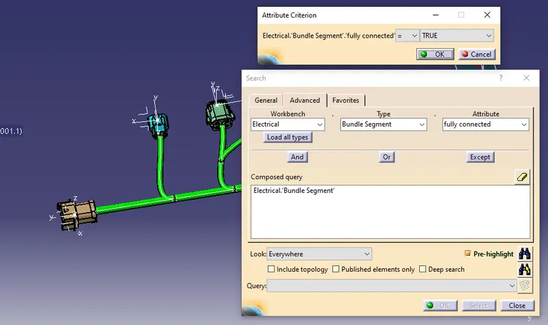
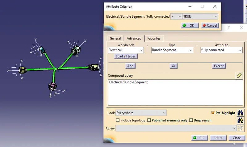
- After Harness A and Harness B are created, the next step is to check the bundle continuity.
- First, we have to make sure multi-branchable is selected and then we have to go in
- Edit>Search>Advanced>Electrical Workbench>Type-Bundle Segment>Attribute-Fully Connected.
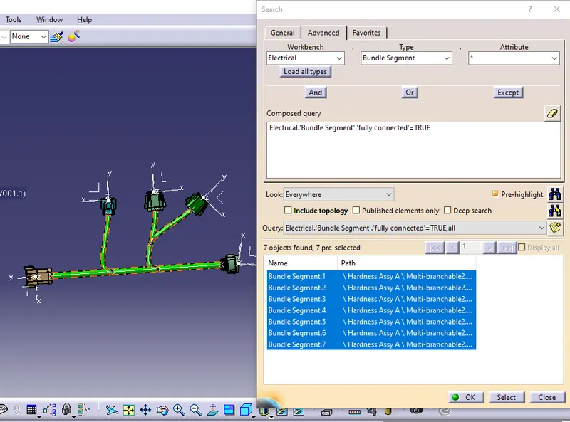
- Selecting the "TRUE" option will show all the connected bundle segments while selecting the "FALSE" option will show all the non-connected bundle-segments.
- Here TRUE option is selected to perform the continuity check.
HARNESS A
HARNESS B
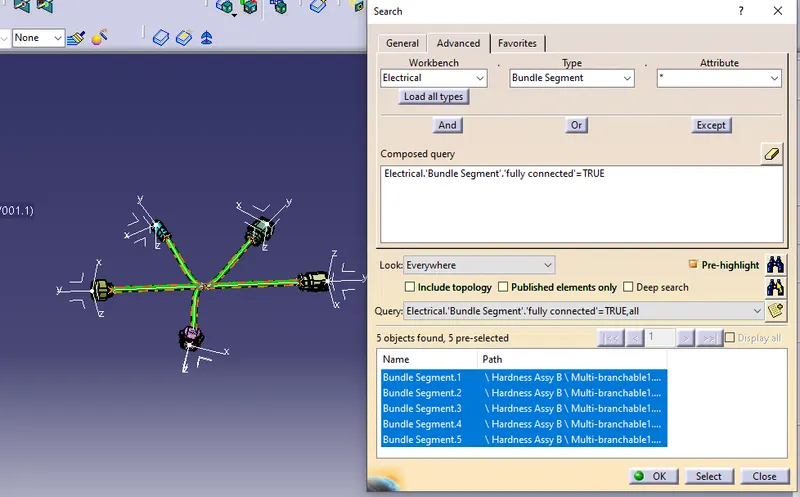
STEP4 - FINAL HARNESS ASSEMBLY
Here we need to create a product file and rename it as Final harness assembly
- Then we need to import both HARNESS A and B into the final product.
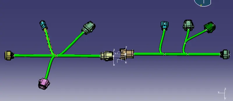
- Then switch to the Electrical assembly design, assemble the Harness A and B by interconnecting the connector 5 and 6 using Connect electrical Devices option.
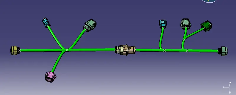
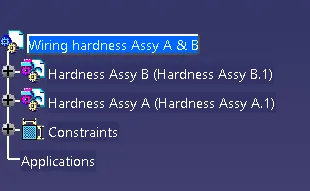
STEP5 - CONVERT IGS FORMAT
In this last step, we have to convert our Final Harness Assembly file into a PART file and IGS format.
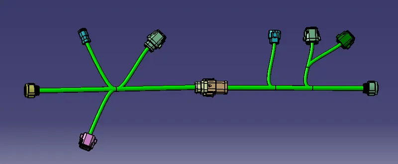
CONCLUSION:
Here, The electrical connectors were defined with necessary properties and Created two harness assembles from the given layout and connected with a connector. then checked bundle continuity, bundle warnings and annotations, finally changed to part file and .igs file format.