Wiring harness design in CATIA V5 - 3D modeling Week 5 & 6 Challenge
Objective-
Route the following harness layout in Electrical workbench. Make assumption for harness bundle diameters. Use the connectors provided. After completion of routing,
- Check the bundle Continuity. Add snap of result in submission
- Add annotation to all connectors. Make an assumptions for annotations like connect 1 , 2 etc
- Check for the bundle warning. Add snap.
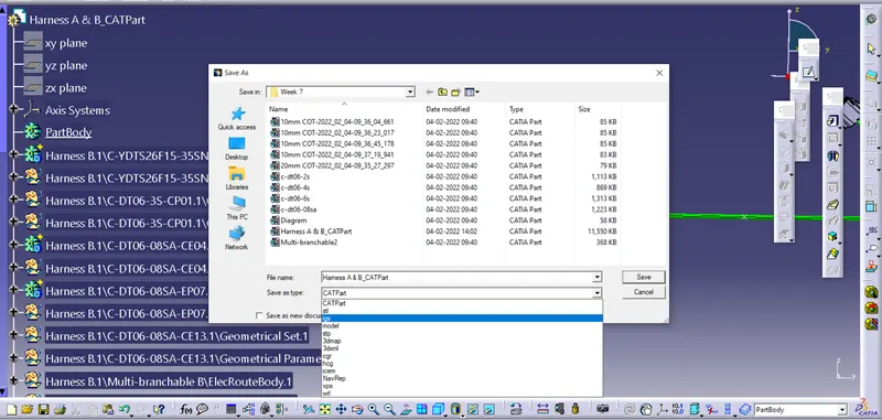
- Generate CAT.part of harness assembly and convert is in. igs format.
Process-
1. Define the connectors
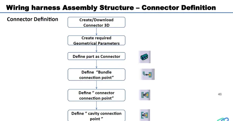
a) Download Connector 3D Part from www.te.com
- DT06-4S
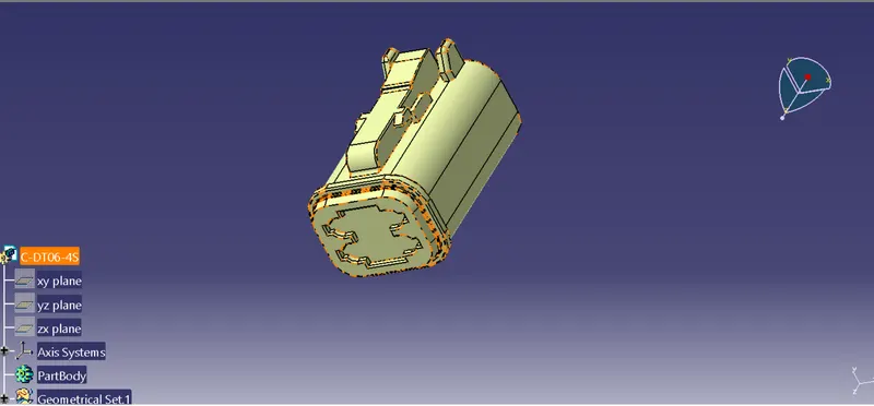
b) Create a Required Geomtrical parameters- Point, Axis Systems
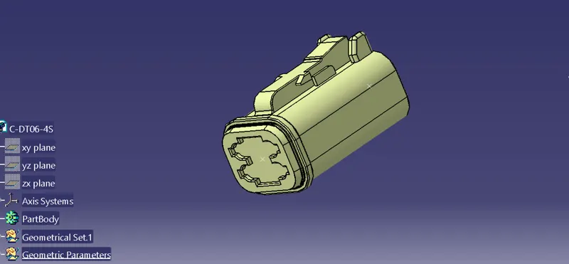
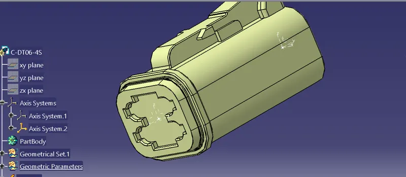
c) Define Part as a connector
Switch from part workbench to Electrical Part workbench, Using the Define connector command to define the connector as a Electrical component
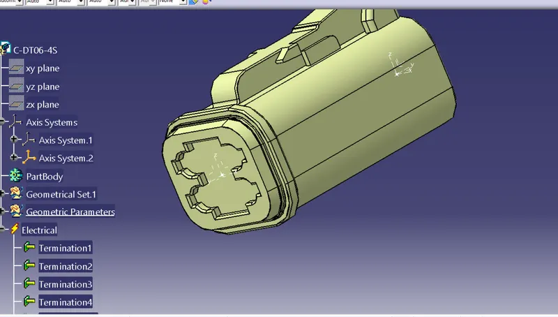
Define the Bundle Connection point and Connector connection Point
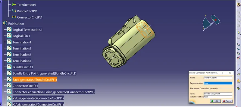
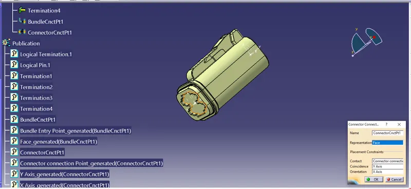
a)Exit all components in that By using Exit component command
b) Switch from Part assembly to Electical Harness Assembly workbench
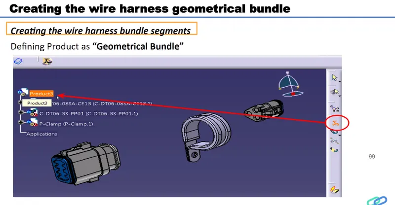
c) Using the Geometrical Bundle command Convert the product as Geomtrical Bundle for (Harness B) and (Harness A)
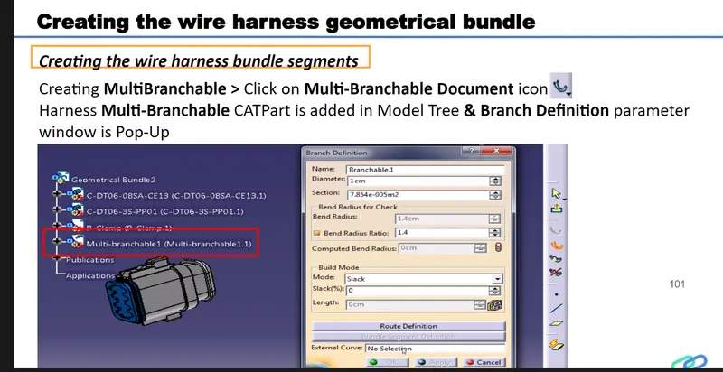
d) Using the Multi Branchble component Command to create the Bundles .
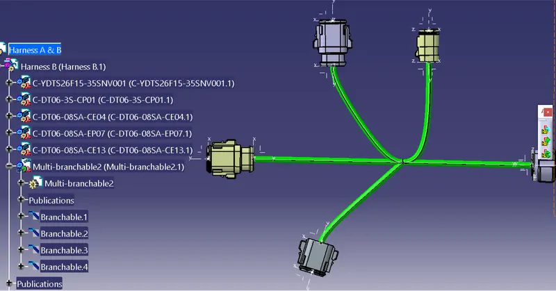
Harness B
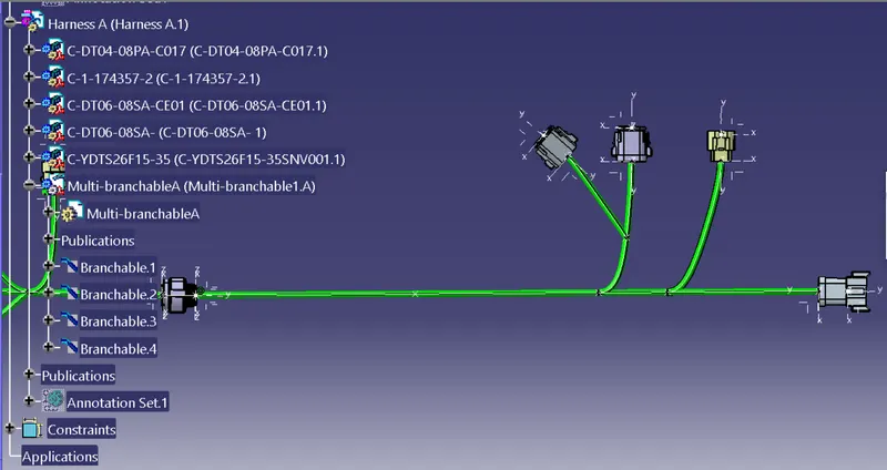
Harness -A
Total Product Assembly Harness A & B
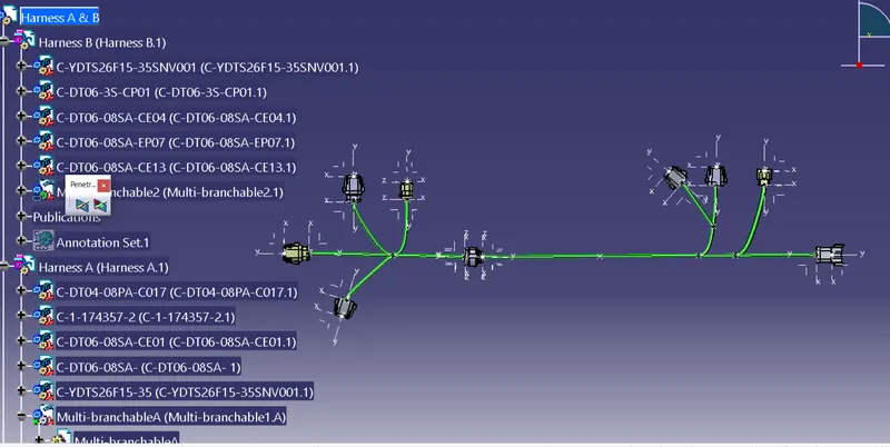
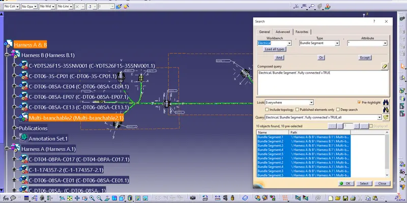
1. bundle Continuity checking
Go to the Edit - Search - Advanced
2. Add annotation to all connectors
Go the Annotation tool bar > Create the New Anottation Plane > Implement the Process
For Harness B
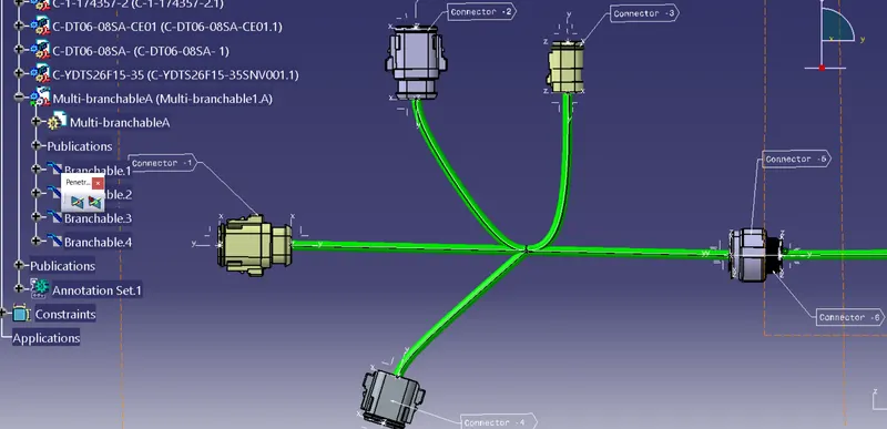
Harness A
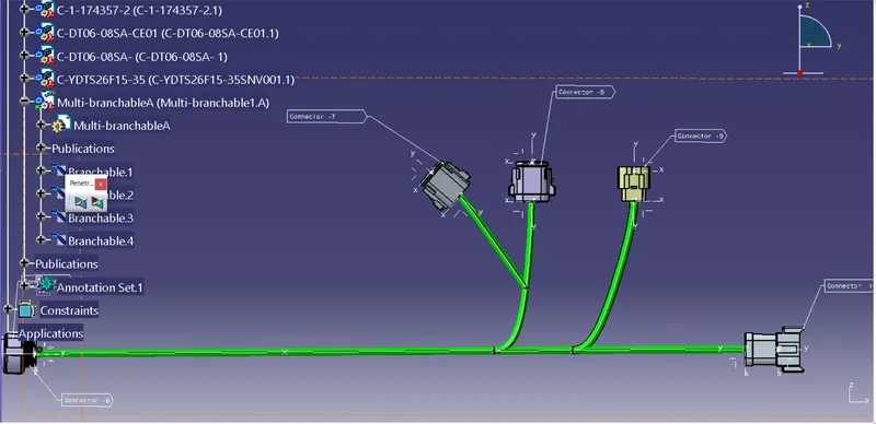
Harness A & B
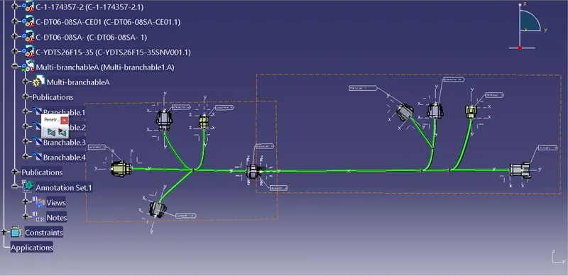
3.
Bundle warning Sign Shows yellow exclamation Mark ! on the Multi banchable product.
And also Showed the Bundle As Red colour
Hear Not Showed the Any Error
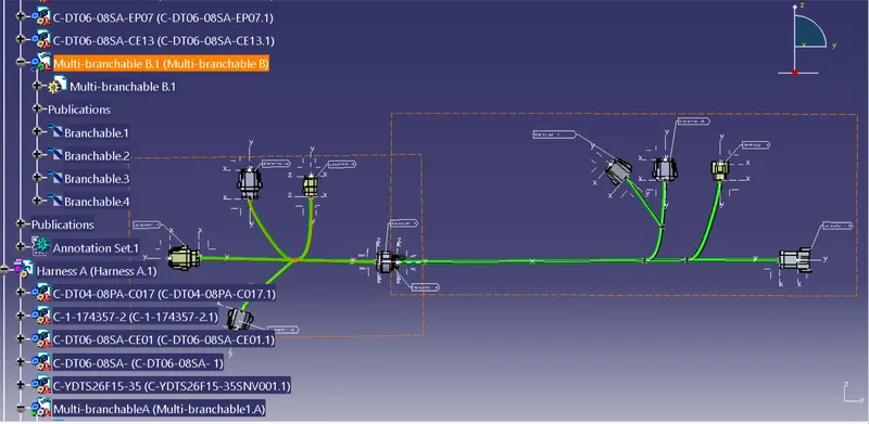
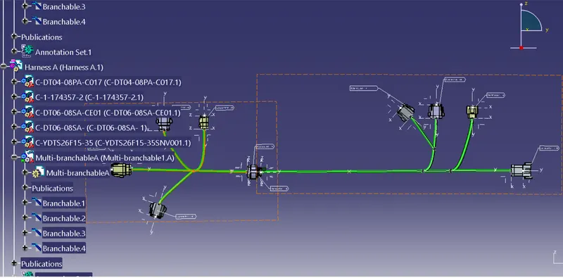
4.Generate CAT.part of harness assembly
Go to the Mechanical Assembly workbench > Tools > General CATpart From Product
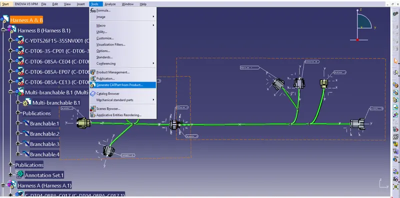
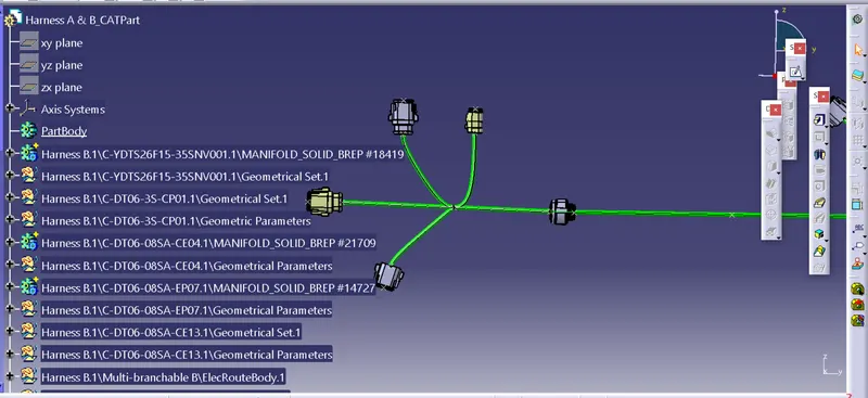
Save As > Igs File