Wiring harness design in CATIA V5 - 3D modeling Week 5 & 6 Challenge
Catalogue Creation
A new CatalogueDocument is created. Two families of COT Tubes(Conduit type), and connectors(electrical type) are defined.
Electrically defining the connectors
The connectors are downloaded from the provided link and is opened in the Catia V5 software. Referance points and axis system are created which are necessary for defining the connector connection point and bundle connection point of the connector. In the Electrical part design workbench, the parts are defined as electrical connectors. The connector connection point and bundle connection point of the connector are defined with the help of previously defined points and axis systems. The connectors are added to the catalogue in the connector family.
Electrical Harness Assembly Creation
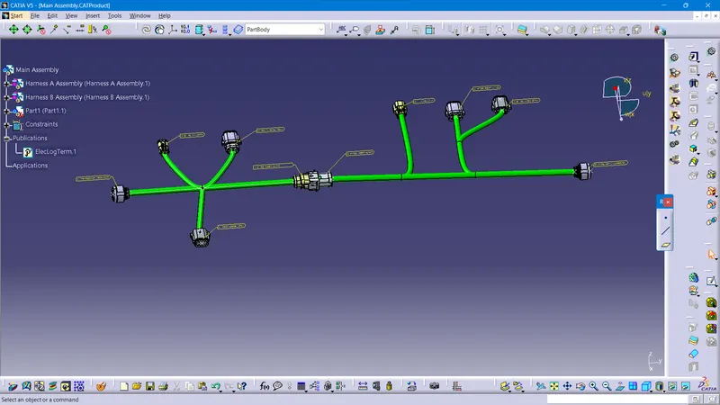
A new product file named 'Main Assembly' is created. A product file named 'Harness A Assembly' and 'Harness B Assembly' is added to the product file. All the connectors which are electrically defined are inserted to to thier respective harness assembly files. This product is electrically defined as Geometrical bundle in the Electrical Harness Assembly workbench. The connectors are moved to the and oriended as given in the picture in question using tools in Assembly workbench. And the bundle segments are created to connect the connectors. Finally in the Main Assembly, the products are aligned properly and the connectors 5 and 6 are electrically connected in the Electrical Assembly workbench.
Bundle Continuity checking
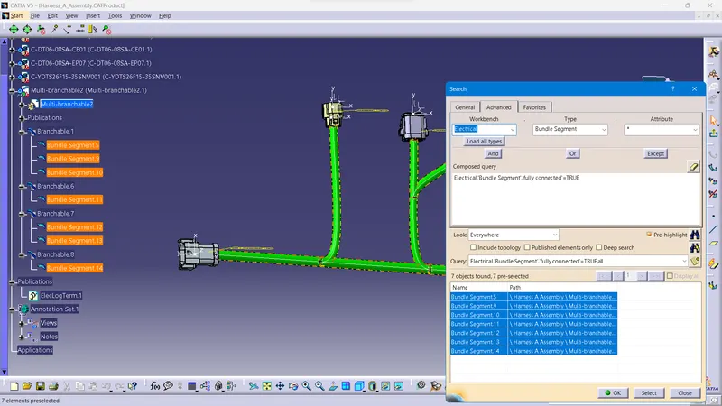
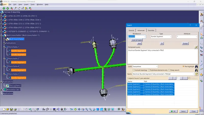
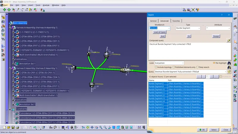
Bundle continuity is checked for the assembly
Harness A
Harness B
Main Assembly :
TRUE
False
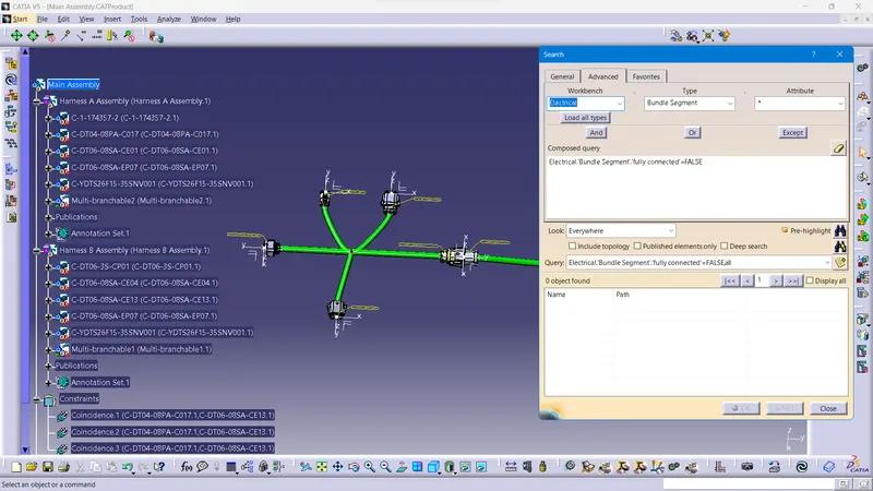
Bundle Warnings
1.
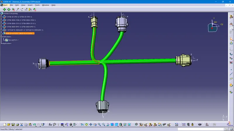
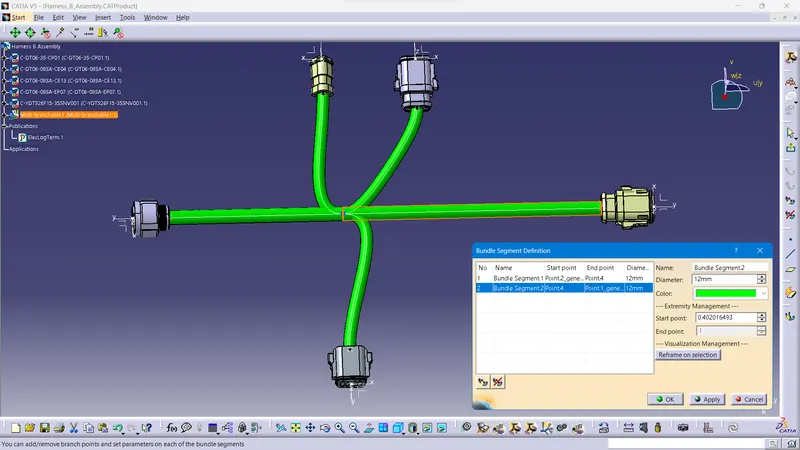
Solved by moving the branching point
2.
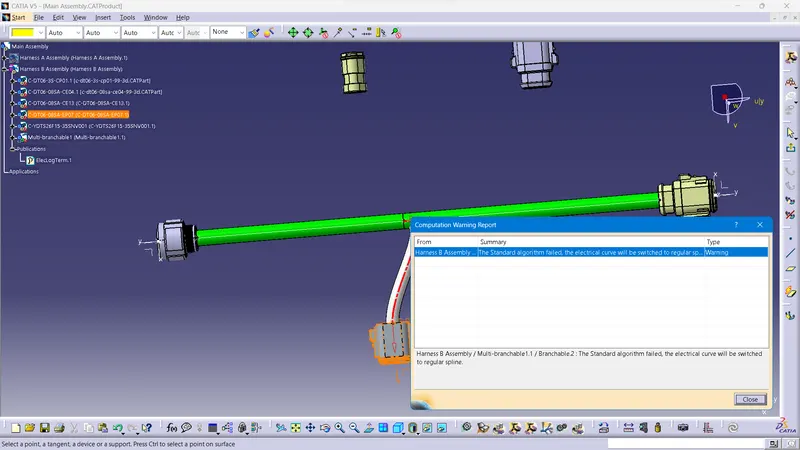
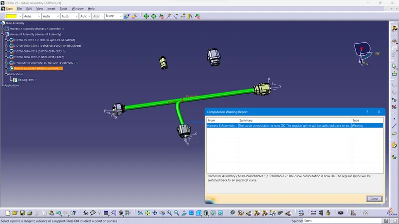
Solved by changing the tangent direction
CAT Part is created using generate CAT Part command and converted to .iges format for the accessing the file in other softwares.