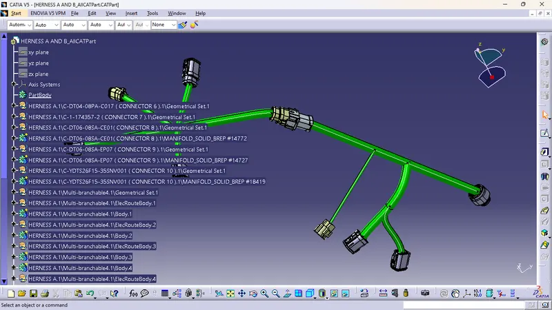
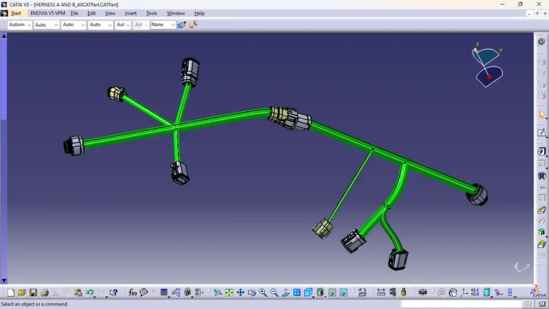
Wiring harness design in CATIA V5 - 3D modeling Week 5 & 6 Challenge
1. create a required geomatrical parameter
2. defined as aconnector
3. defined bundle connection point
4. defined a connector connection point
5. then sketch the given diagram in part design
6. the arrenged the connector in in the given sequence using snap tool
7. After all the connectors are defined, the workbench was switched to Electrical Harness Assembly where Geometrical Bundle was activated. All the connectors were routed using the Multi-Branchable Document command. and herness A and herness B connected using connect ellectrycally device