Wiring harness design in CATIA V5 - 3D modeling Week 5 & 6 Challenge
AIM:
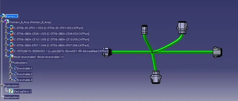
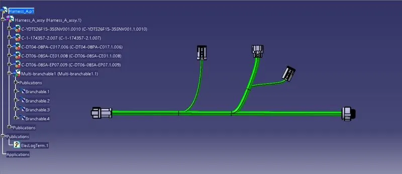
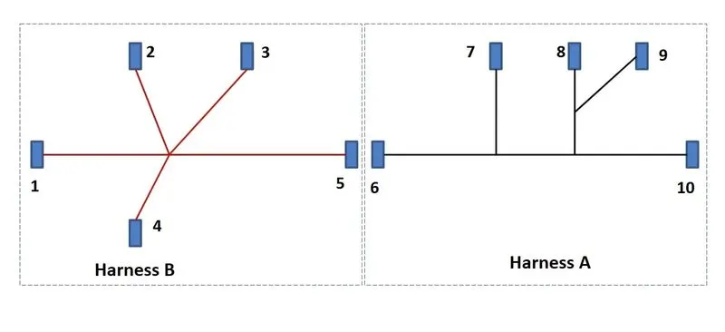
From the above diagram we can conclude that the connectors should connect accordingly by following the 2D routing mapping
PROCEDURE:
As for the above diagram Harness A&B we have to downlode the connectors
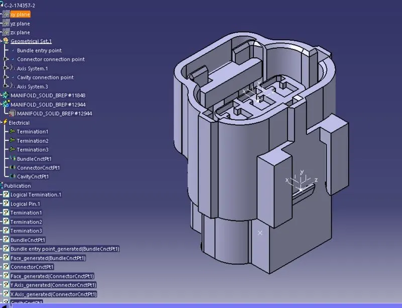
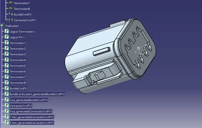
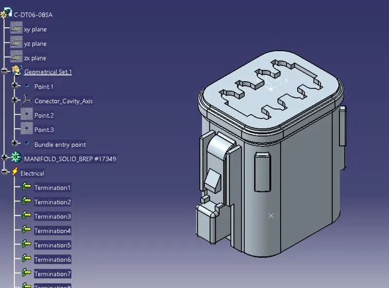
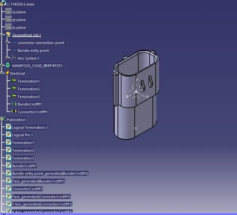
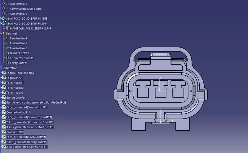
make sure that conector should have electrical properties and eelectrically defined
now, take all the connectors togather in product file in the assembly and make it into correct position
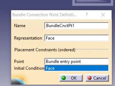
make sure all the bundle connecting points and connector connecting points are properly given
if the connectors are not defined properly then it is impossible to give the routing in the electrically defined workbench
once all the process is completed then we can start giving routing connections
while giving the routing connections we should define bundle segment from connector to connector
if we want add branches then we should add branching point to the main branches and then define the add branch to the connecting point
By this way wecan define all the coonectors and branch segments.
once the routing is completed for the Harness A and B then we should assemble both A & B harnesses make it into one single routing.
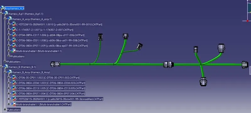
Some of the routings, connectors pictures and feature defined tree: