Wiring harness design in CATIA V5 - 3D modeling Week 5 & 6 Challenge
INTRODUCTION TO WIRING HARNESS DESIGN USING CATIA V5
OBJECTIVE: The objectives or motives if this challenge are listed below
- To download all the listed connectors from the website.
- To define the connecots electriclly in the electrical part workbench.
- To add all the connectors into the connectors catalogue.
- To create harness A according to the reference image.
- To create harness B according to the reference image.
- To assemble harness A and harness B electrically in the electrical assembly workbench.
- To convert the the assembly into a solid part by saving it as a step or igs file.
- To name the connectors in the mechanical assembly workbench.
- To prepare a report explaining all the procedures by including images.
WIRING HARNESS :
A wire harness, often referred to as a cable harness or wiring assembly, is a systematic and integrated arrangement of cables within an insulated material. The purpose of the assembly is to transmit signal or electrical power. Cables are bound together with straps, cable ties, cable lacing, sleeves, electrical tape, conduit, or a combination thereof. The wire harness simplifies the connection to larger components by integrating the wiring into a single unit for “drop-in” installation.
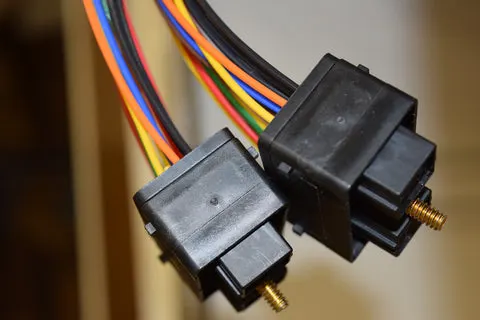
CONNECTOR :
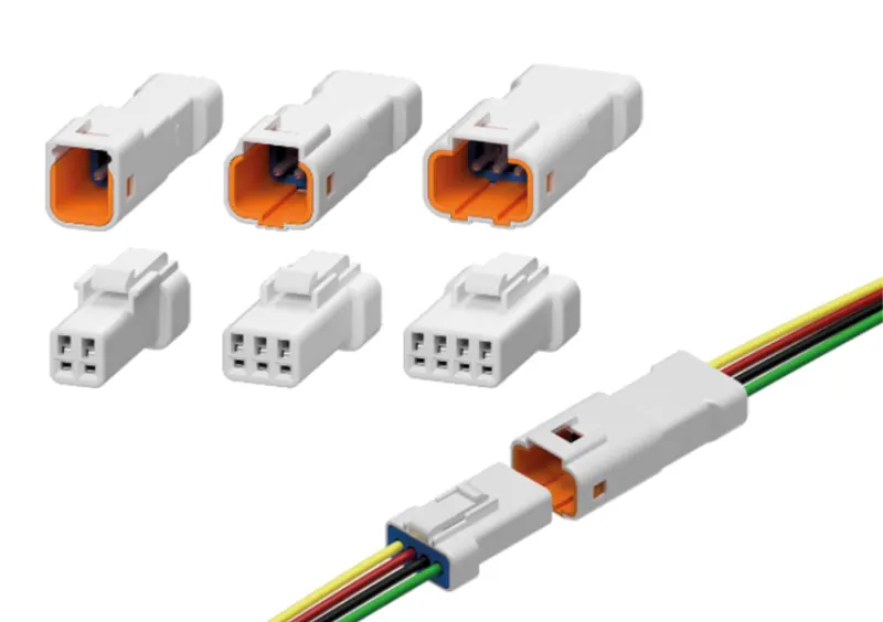
Connectors are the electro-mechanical devices used to form a continuous electronic signal to connect wire harnesses to a power source or circuit. On a basic level, connectors consist of male-ended plugs and female-ended jacks that can be joined together to relay an electronic signal.
In general these are plastic molded housing with locking and retention features.
Connectors attach to or pass the wires through a component. They are water and heat resistant. A hard outer shell with a locking clip holds two halves of a connector together. The pins and sockets are crimped to the wire both at the insulation and the bare wire. They are made so that they fit together perfectly, but can also be easily disconnected when needed. A rubber seal encloses all the wires and keeps the wires protected from moisture and other abrasive conditions.
The steps followed in this challenge are explained in the below flowchart,
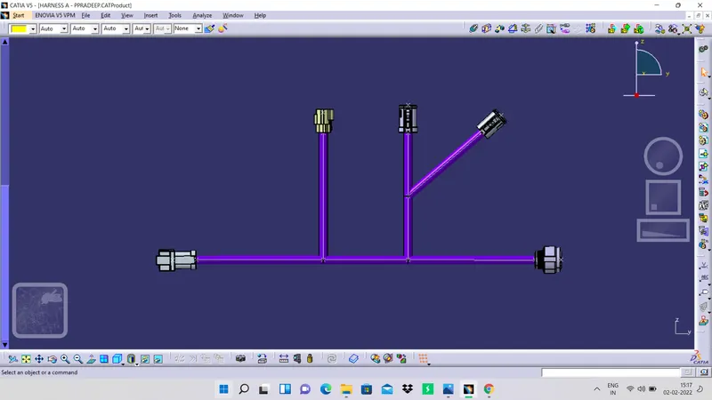
The image of harness A is given in the below picture,
The arrangment of harness B is shown in below figure,
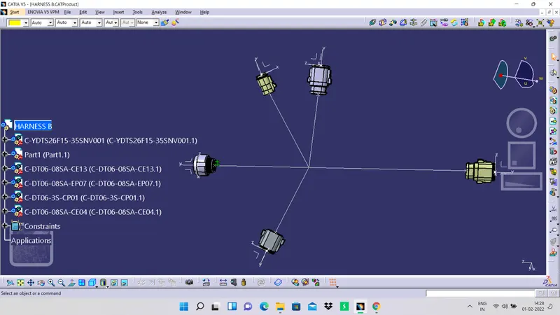
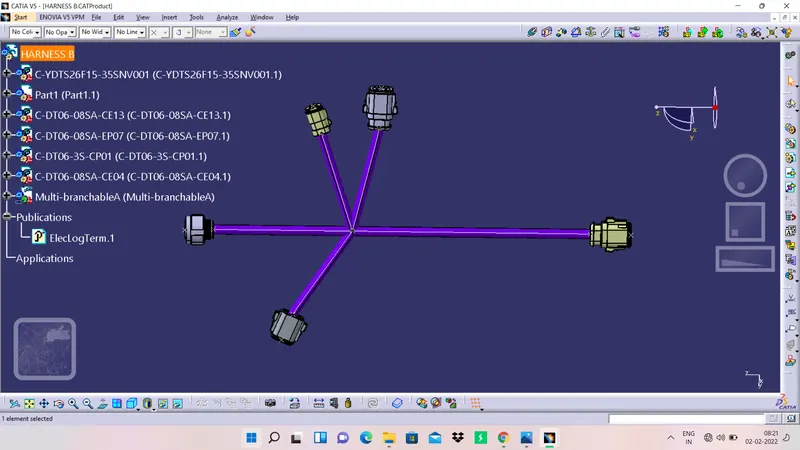
The image of harness B is as shown in below figure,
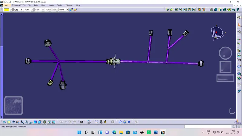
The assembly of these two harnesses is shown in below picture,
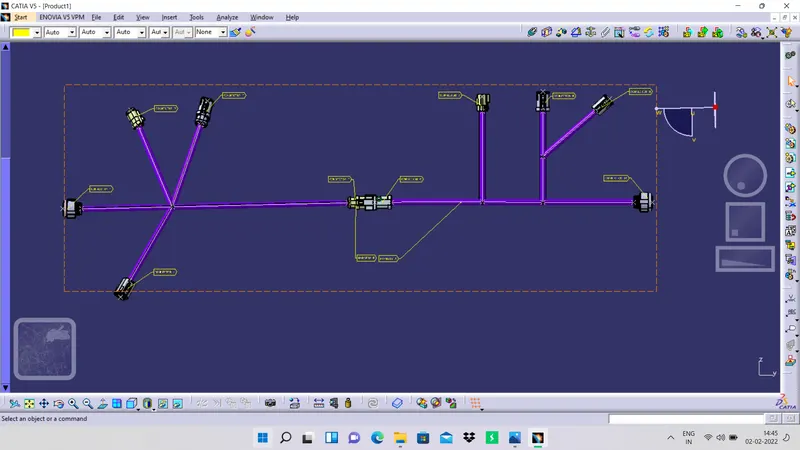
The image of harness after naming in the mechanical assembly workbench is sown in below picture,
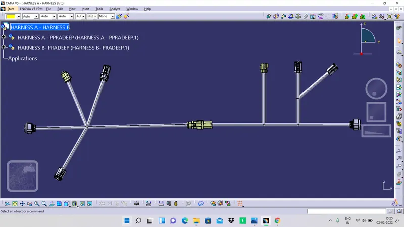
the image of converted part file is shown in below figure,
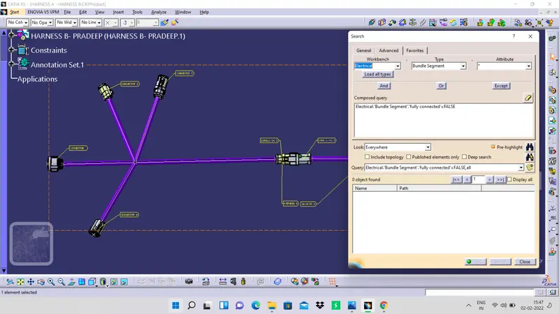
The image of bundle segment connection has been attached in the below figure,
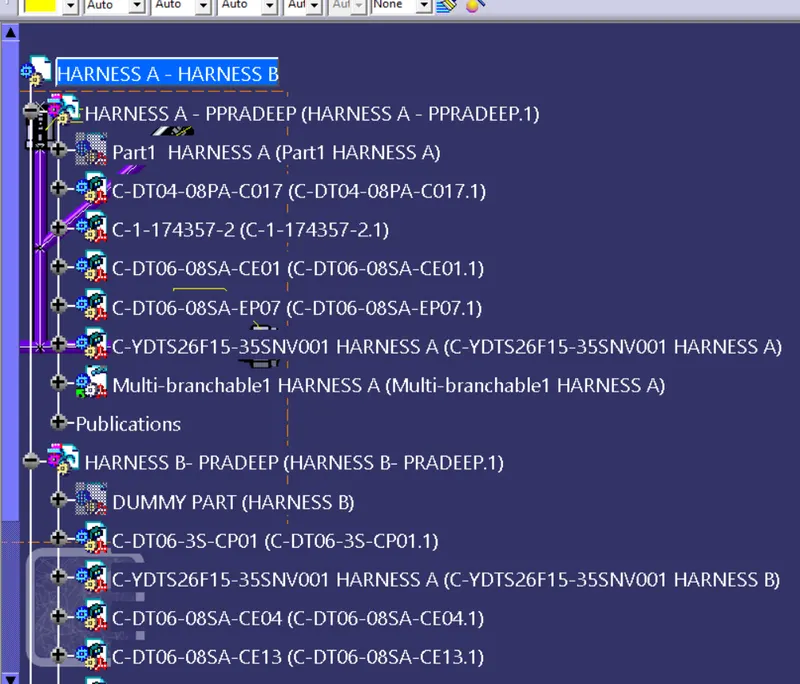
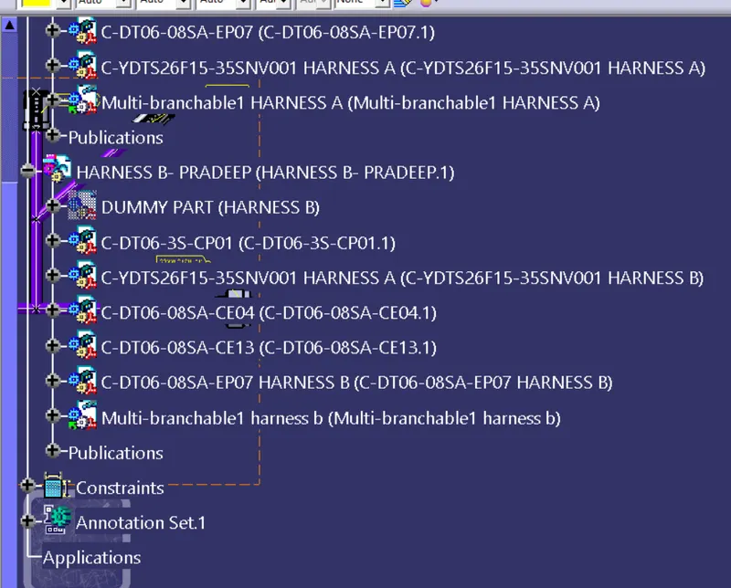
The tree structure of the final assembly is attached in the below images,
CONCLUSION
And hence, all the objectives of this challenge has done and files are attached to the challenge successfully.