Wiring harness design in CATIA V5 - 3D modeling Week 5 & 6 Challenge
Q1. Route the following harness layout in Electrical workbench. Make assumption for harness bundle diameters. Use the connectors provided. After completion of routing,
- Check the bundle Continuity. Add snap of result in submission
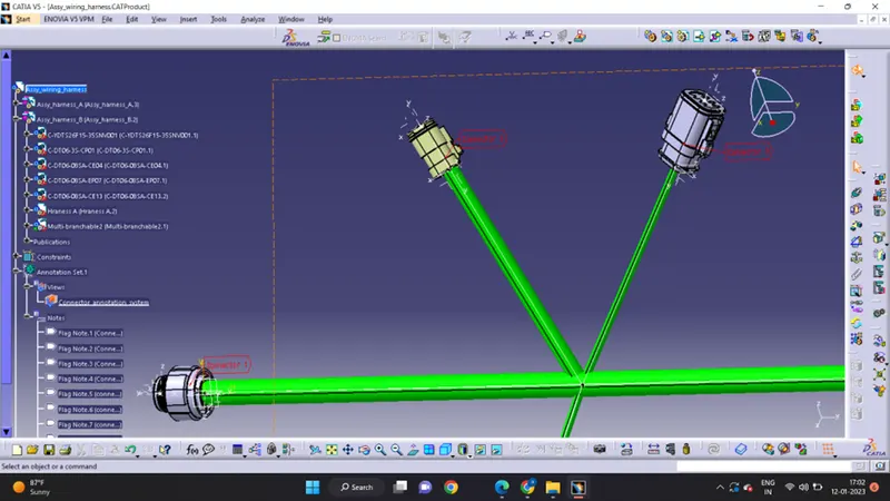
- Add annotation to all connectors. Make an assumptions for annotations like connect 1 , 2 etc
- Check for the bundle warning. Add snap.
- Generate CAT.part of harness assembly and convert is in. igs format.
Ans:
Before going to start electrical routing of two harnesses (A & B ) downloaded all needed connectors from provided link in the question.
sketch of the layout of harnesses A & B are as follows
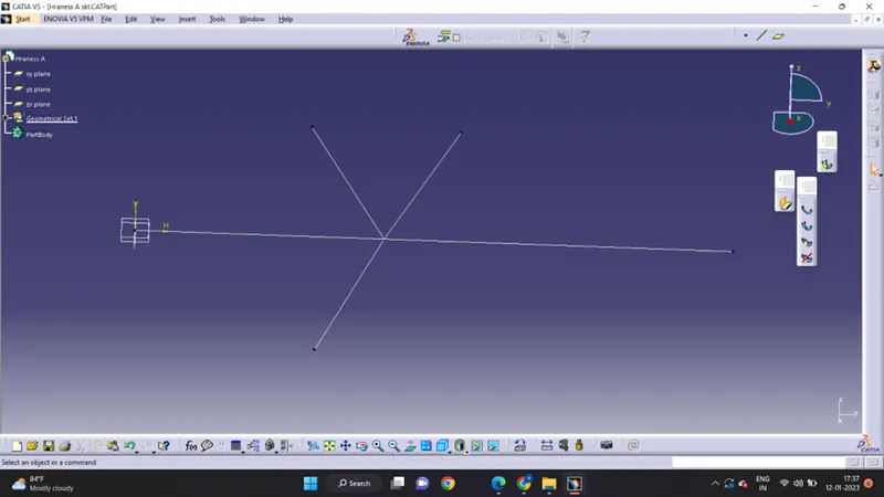
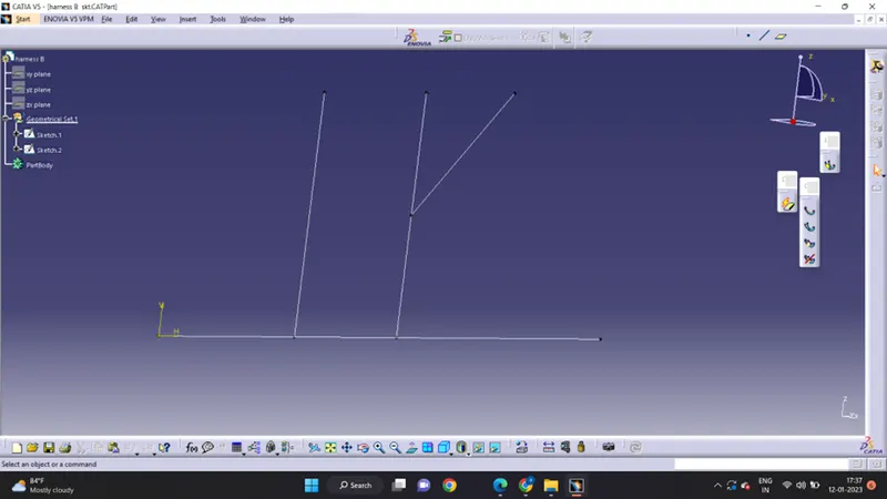
after that define all connectors as electrical components by providing a bundle connection point & connector connection point
created assembly of harness A and Harness B after that male-female connector was connected in the electrical assembly
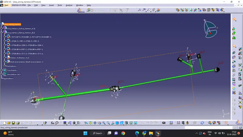
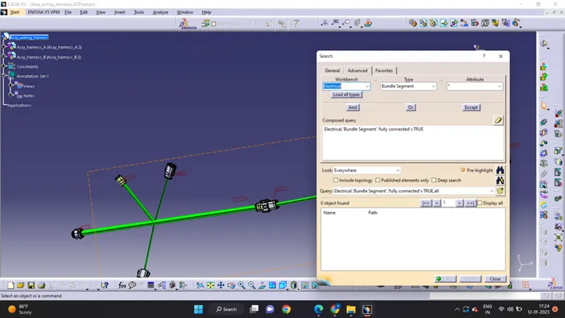
Connectivity is checked by the following flow
Edit -> search -> advanced -> select the parameter you want to check
Annotations added as connector numbers are shown in fig. below
Saved file as in igs. Format
Assy_wiring_harness.igs