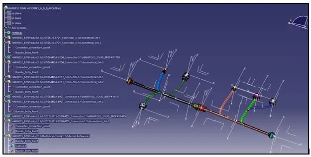
Wiring harness design in CATIA V5 - 3D modeling Week 5 & 6 Challenge
Creation of Bundle Routing for the connectors and harness assembly
The Connectors to be defined electrically are to be created or 3D part file is to be downloaded from the respective websites.
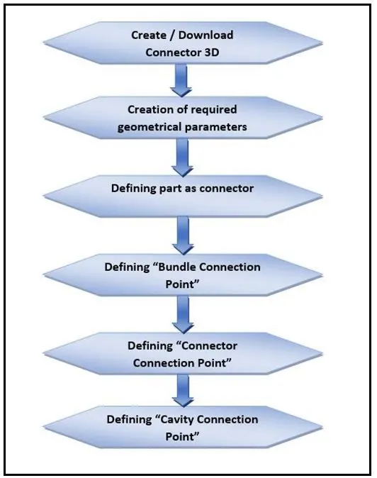
The process for connector definition in CATIA is shown below,
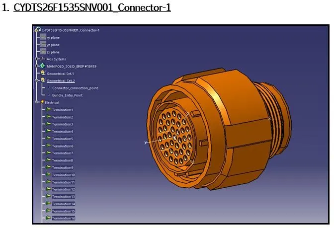
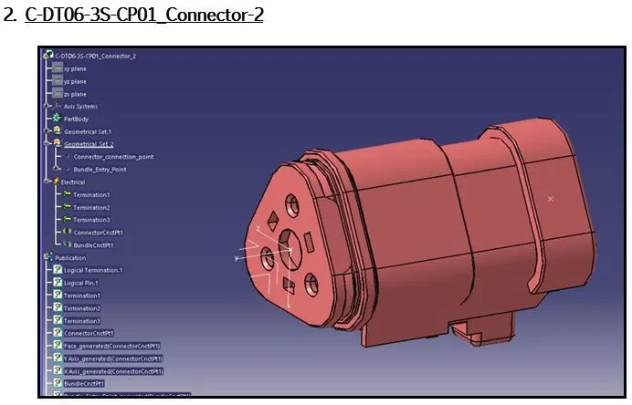
The connectors which are defined electrically is shown below,
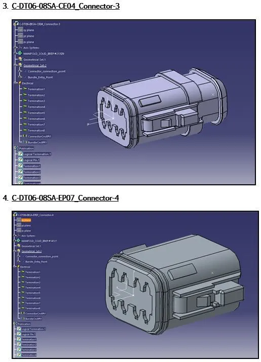
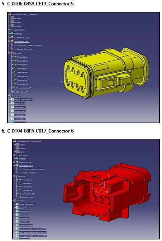
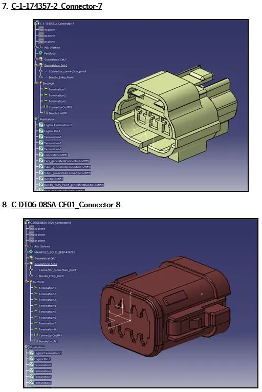
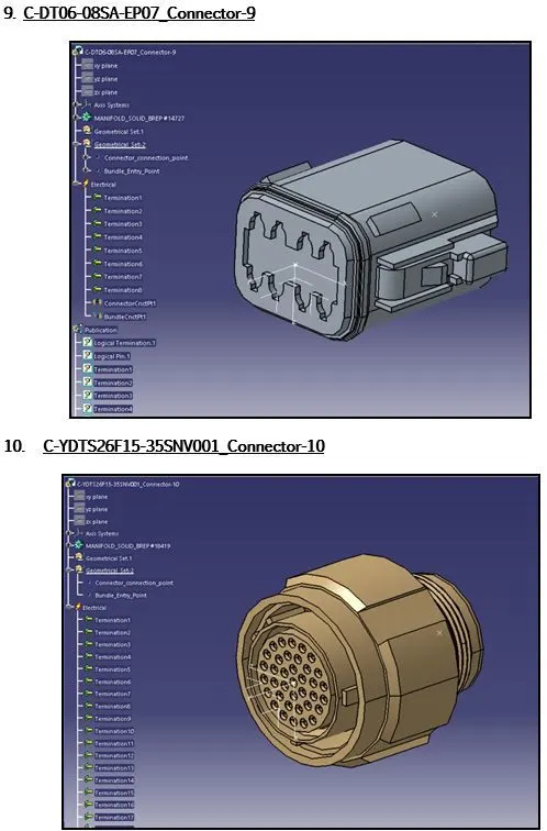
Bundle Routing of connectors in electrical harness assembly workbench.
Preparation of harness assembly
The Wiring harness product assembly contains the following components,
- The harness context assembly.
- Geometrical Bundle.
- Electrical Bundle.
- The harness context assembly: -
The Harness context assembly is the top-level product file that contains the harness geometrical bundle and the wire harness electrical bundle.
- Geometrical Bundle: -
Geometrical bundle is the sub level product which contains all of the harness components. i.e., clips, supports, splices, grommets, annotation and actual physical bundle segments and branches.
- Electrical Bundle: -
Electrical Bundle is a sub-product file, which contains all of the electrical circuit information.
- Defining of the wire harness routing.
Conditions to be adhered for wiring harness routing is shown below,
- Geometrical Bundle assembly is to be completed.
- All components are placed at desired locations.
- All type of electrical connections/constraints are defined.
- Background Geometry Data is available and assembled in Geometrical bundle context assembly.
- All clips / clamps /channels are placed at desired locations.
We have to know create two harness assembly using the above electrically defined connectors,
There are two type of HARNESS SUB-ASSEMBLIES that has to be created as per the below electrical schematic drawing,
- HARNESS-A
- HARNESS-B
The preparation of bundle routing for the connectors, which are electrically defined is to be done as per the electrical circuit drawing provided below,
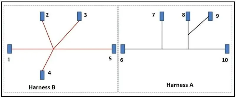
Both the harness sub-assemblies (HARNESS-A & HARNESS-B) has to be electrically connected to form a single main harness assembly.
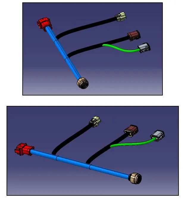
1.) HARNESS-A Assembly
The assembly of the electrical defined connectors is made under the sub-assembly – product named “geometrical Bundle assembly”
The bundle routing is initiated as per the electrical circuit drawing shown above.
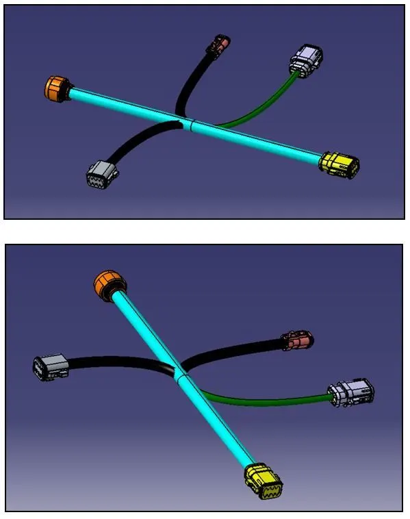
2.) HARNESS-B Assembly
The Harness-B assembly is created by using the electrical defined connectors belonging to Harness-B as per the electrical circuit diagram. The diameter of the Bundle segments is selected based on assumption.
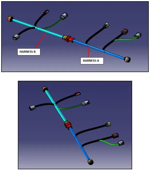
MAIN HARNESS ASSEMBLY (Harness-A & Harness-B)
The Harness-A and Harness-B are the sub-assemblies of the main harness assembly, where both the Harness-A and Harness-B are electrically connected to form a single harness entity.
The Main Harness assembly with electrically connected Harness-A and Harness-B sub-assemblies are shown below,
Bundle Continuity analysis for HARNESS-A and HARNESS-B
The Bundle Continuity is analysed for both Harness-A and Harness-B by using the “Search” command in CATIA which is available in ’EDIT’ option present in toolbar.
The Bundle segments are connected as per the assembled position of connectors shown in the electrical circuit diagram.
The “Search” command has a sub-option named “advanced”, which helps to filter certain conditions helping to check the bundle continuity for HARNESS-A and HARNESS-B.
The Composed Query in Advanced search has the logical condition which helps to know, whether the connectors are connected electrically with the bundle segments.
a.) HARNESS-A – Bundle continuity Check
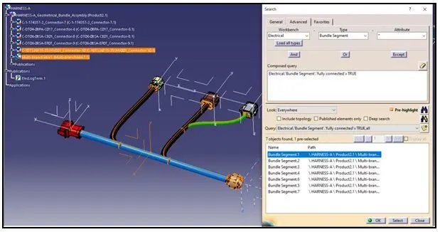
The above bundle continuity check for HARNESS-A has passed the logical condition of “fully connected”, thus indicating that all the bundle segments are connected with no discontinuity.
b.) HARNESS-B – Bundle continuity Check
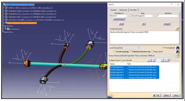
The above bundle continuity check for HARNESS-B has passed the logical condition of “fully connected”, thus indicating that all the bundle segments are connected with no discontinuity.
Annotation Display for connectors of HARNESS-A and HARNESS-B
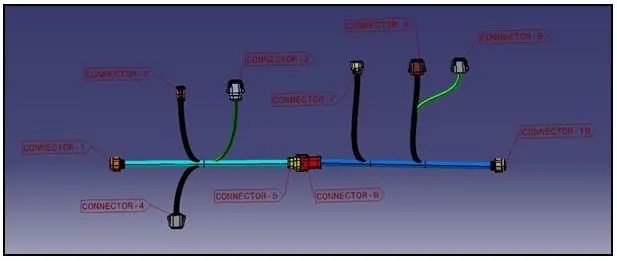
The MAIN electrical assembly of Harness-A and Harness-B is represented by adding annotations to all the connectors.
The annotations makes the identification of connector location as shown in the electrical circuit diagram.
There are different options available in CATIA for projecting the annotations to make the user easier to co-relate the assembly/part with the schematic drawing.
The annotations added to the MAIN HARNESS ASSEMBLY is shown in below figure,
CATPart generation for MAIN HARNESS assembly and conversion of CATpart into IGS format
For the MAIN HARNESS ASSEMBLY the CATPart was generated using the command “generate the CATpart using product..”.
After saving the CATPart file, the IGS conversion was made for the same to access in all the design tools like – SOLIDWORKS, UG-NX, etc.