Wiring harness design in CATIA V5 - 3D modeling Week 5 & 6 Challenge
REPORT
Aim : To route the harness layout in given format using Electrical workbench.
Also,
- To Check Bundle Continuity.
- Add Annotation wherever necessary.
- To check for the Bundle warning.
- To generate .CATPart from .CATProduct
- To Convert it in .igs format.
First Step
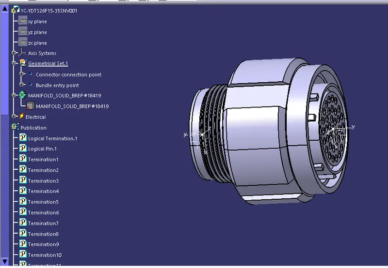
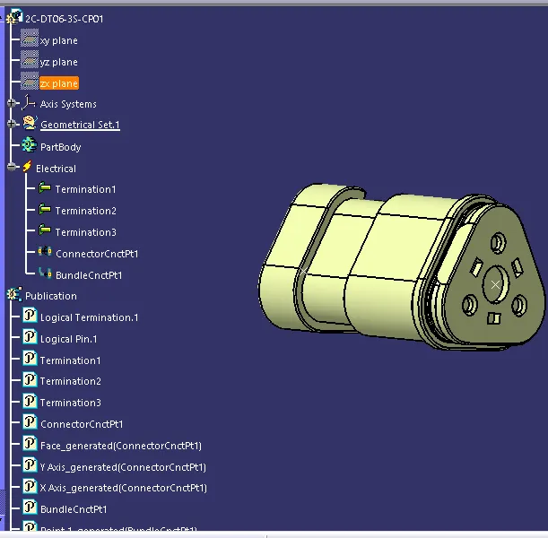
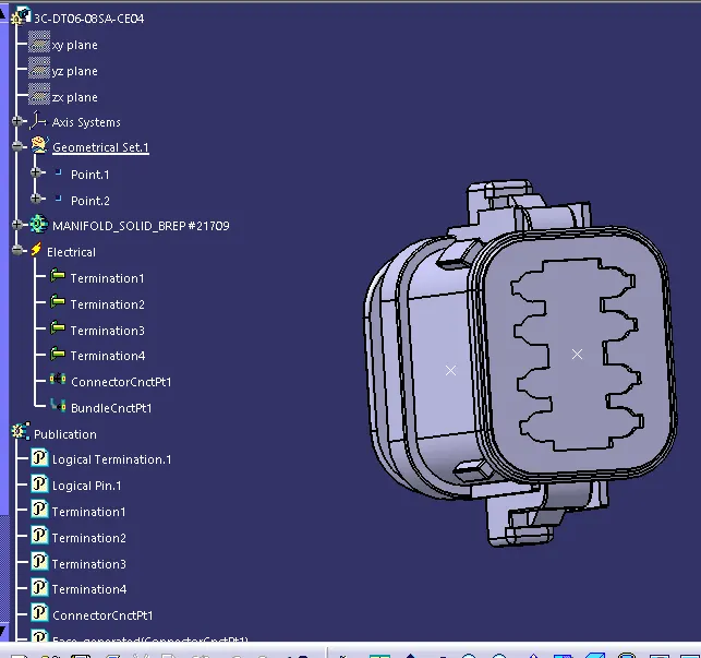
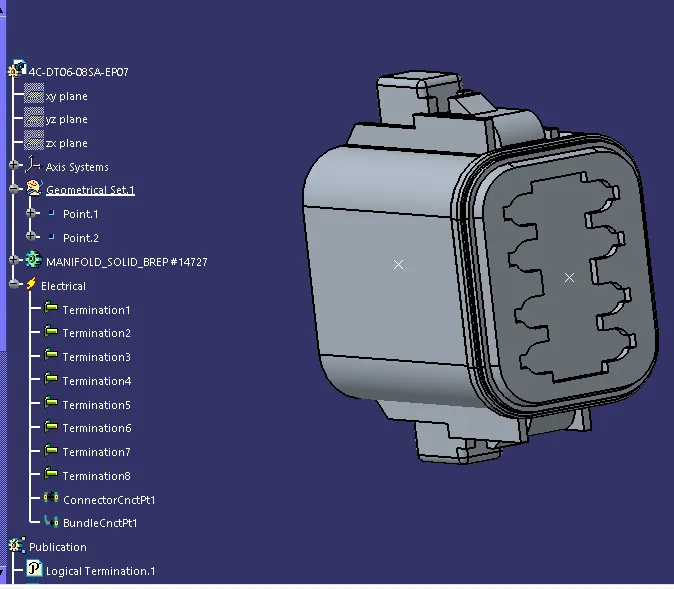
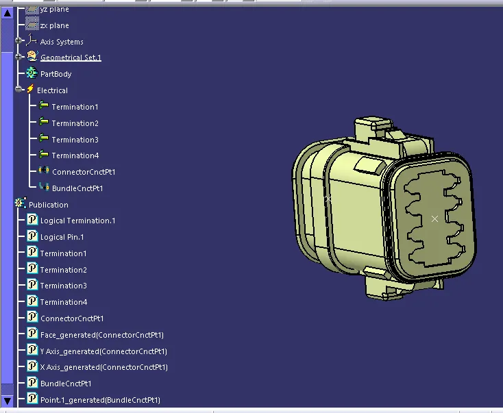
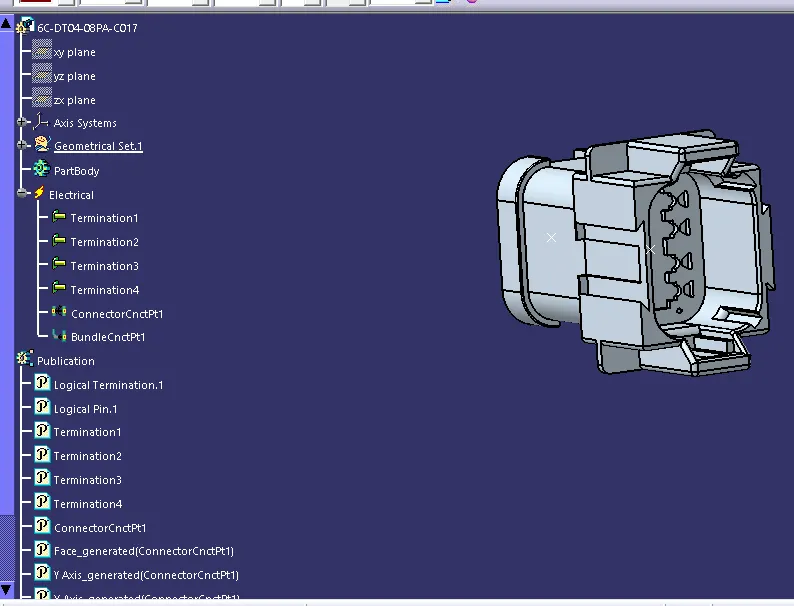
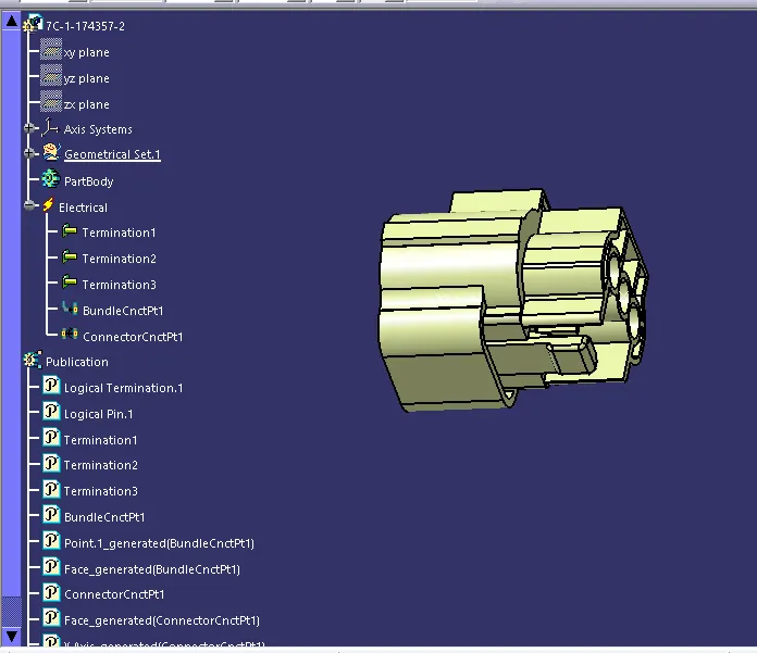
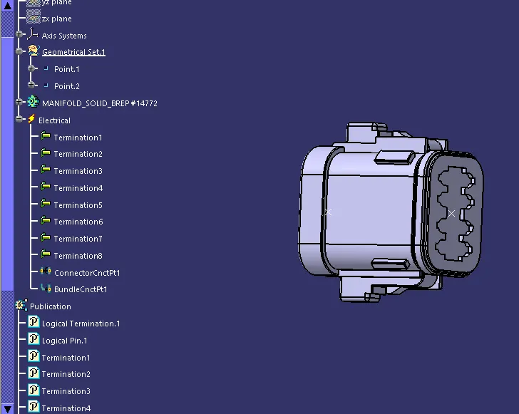
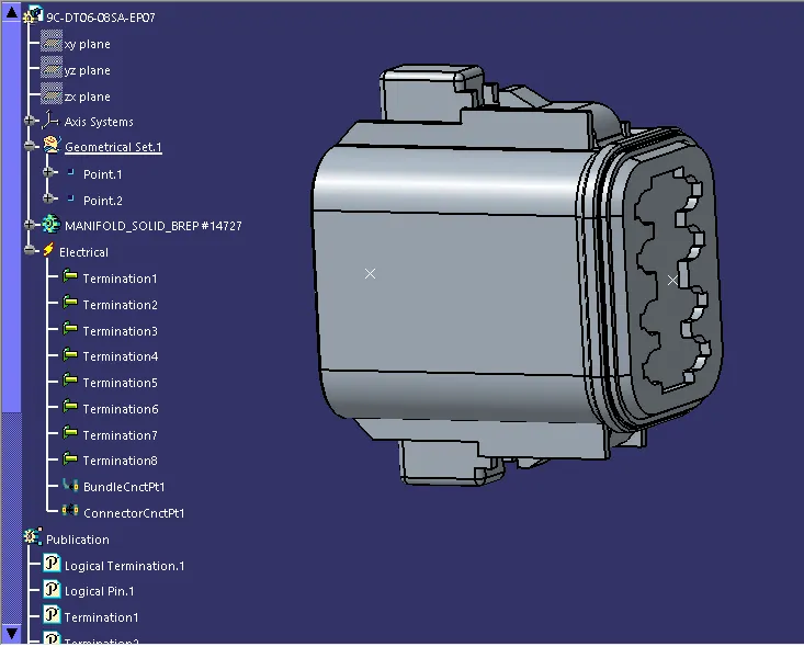
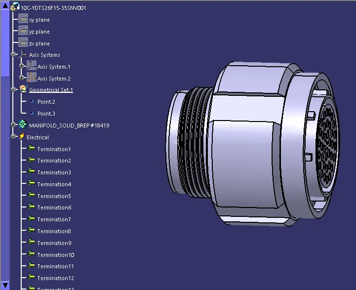
- Download all necessary connector files from Drive link provided in dashboard, or it can be done through te.comwebsite if connector name is known.
- Define as connectors in Electrical part define workbench.
- Define Connector connection point, Bundle entry point for all connectors.
- Save them in the connector catalogue.
Second Step
- In Mechanical Assembly workbench place all connectors in their required location.
- In Electrical Harness Assembly Workbench define Geometrical Bundle and add Multi branchables as per the given layout.
- Double click on Main Bundle so the workbench shifts to Electrical Harness Installation where the branch points can be added.
- Give bend radius ratio as 1.4
- Diameter of 10mm for main branch and 5mm for sub Branch.
- Keep Slack to 0%.
- Give Route Definition in the Correct manner along with that check for orientation of tangent direction.
- The same should be followed even for Harness_B too.
- This finishes the harness installation.
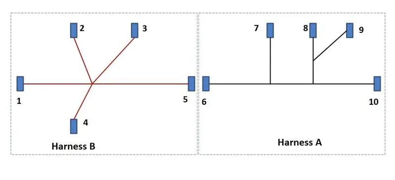
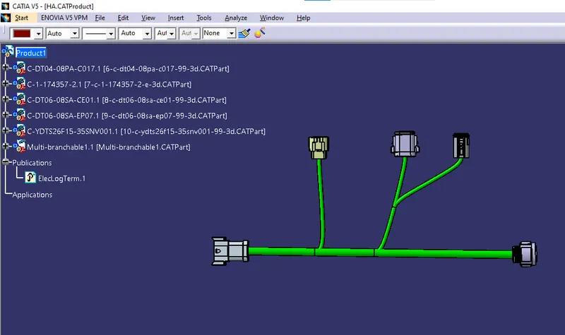 HARNESS_A
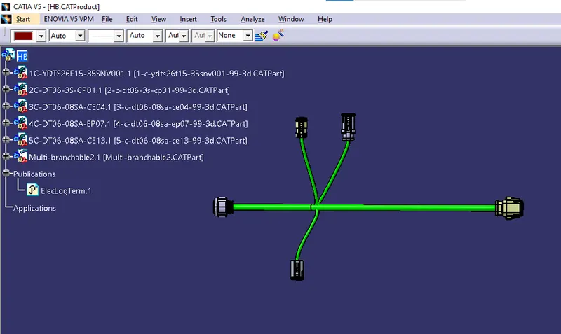 HARNESS_B
Third Step
- Create a New Product.
- Copy Both A and B harness to it.
- Manipulate both in a desired order up-to an extend.
- Go to Electrical Harness Assembly Workbench and use Connect Electrical Devices to connect the Connector_5 and Connector_6.
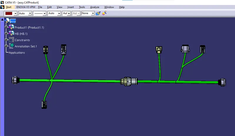
Fourth Step
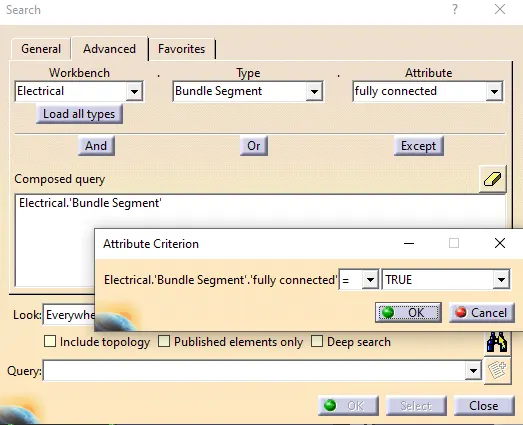
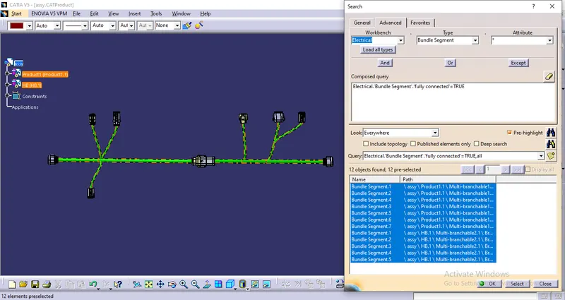
- Check Bundle Continuity using search tool available in edit menu.
- Select the data as shown in picture.
- All connectors are fully connected.
- Check for Bundle Warning, when there is issues with bend radius, bundle diameter and vector positions.
- This error can be visualized by red colour in bundle path or even yellow mark in the tree structure.
- Manipulating Slack could or vector position might solve the issue.
- In my case no issues was found, hence we can proceed.
Fifth Step
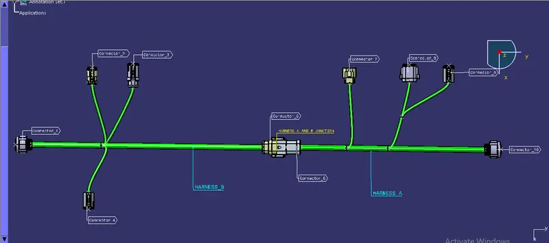
- In assemble Mechanical Assembly Design Workbench, we have a tool for adding annotations.
- Using view from reference the plane is selected for adding annotation.
- Flag note with ladder is selected and the names are addeed as in the below snip.
Last Step
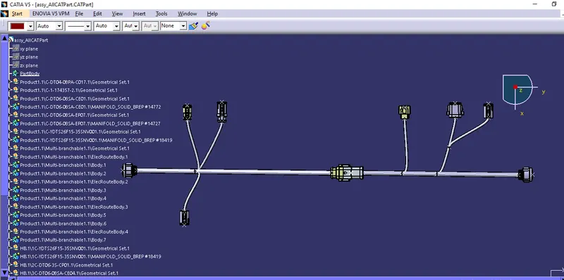
- The CATProduct is converted into CATPart using tool available in tool menu, this gives us geometrical sketch and partbody.
- Now go to “Files” menu, select “save as” and save its as .igs file.
This completes our requirement.