Wiring harness design in CATIA V5 - 3D modeling Week 4 Challenge
Wiring harness design in CATIA V5 - 3D modeling Week 4 Challenge
Aim:
The aim of this project is to route the given electrical harness layout in Electrical workbench. Make assumptions for harness bundle diameters and also add protective covering on all branches connected to connectors as shown in layout below.
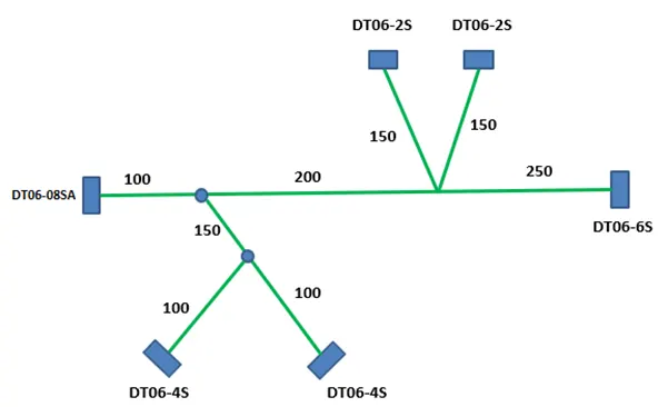
The following 3D connectors data is downloaded from www.te.com
- DT06-4S
- DT06-6S
- DT06-2S
- DT06-08SA
Procedure:
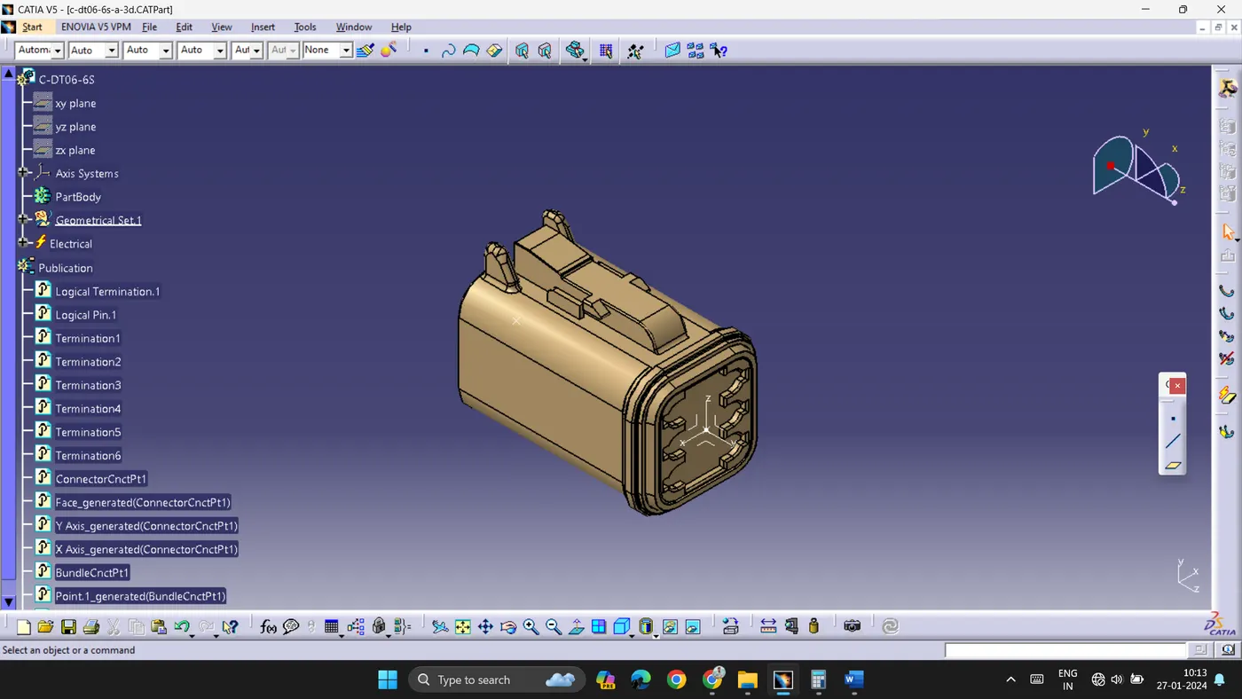
To convert 3D data into electrical component, the following steps are used.
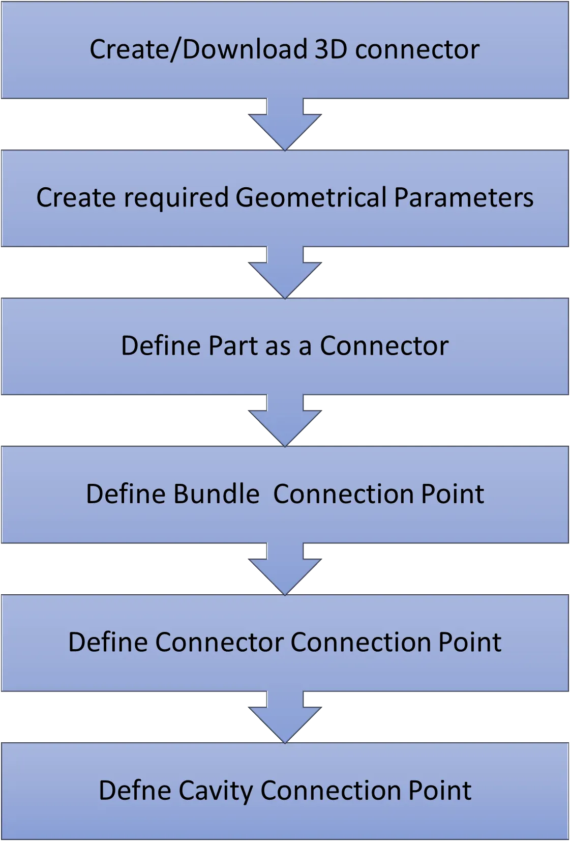
The steps are same for all the components.
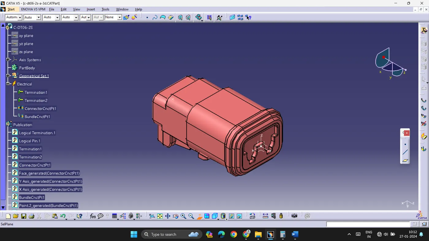 |
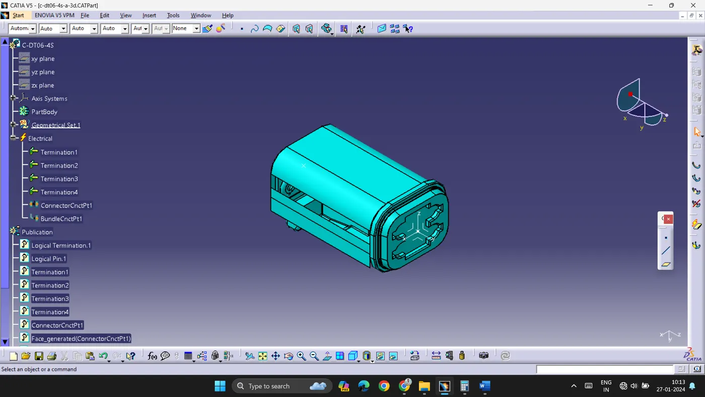 |
 |
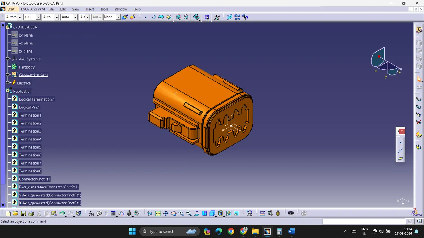 |
- All the connectors are defined as electrical connectors in Electrical workbench.
- In Assembly Design Workbench all the components are arranged according to the given layout.
- To arrange the components tools such as Translation or Rotation and Manipulation are used.
- Branches are created between all the connectors according to the layout.
- Main branch is assumed to have 10mm diameter and its Bend radius ratio is given the value of 1.4.
- The sub branches are given 5mm diameter with same bend radius ratio.
- Using Route Definition, the branches are created with preferable direction.
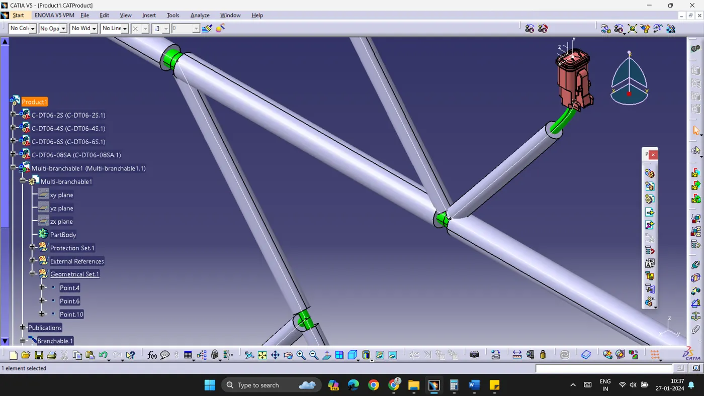
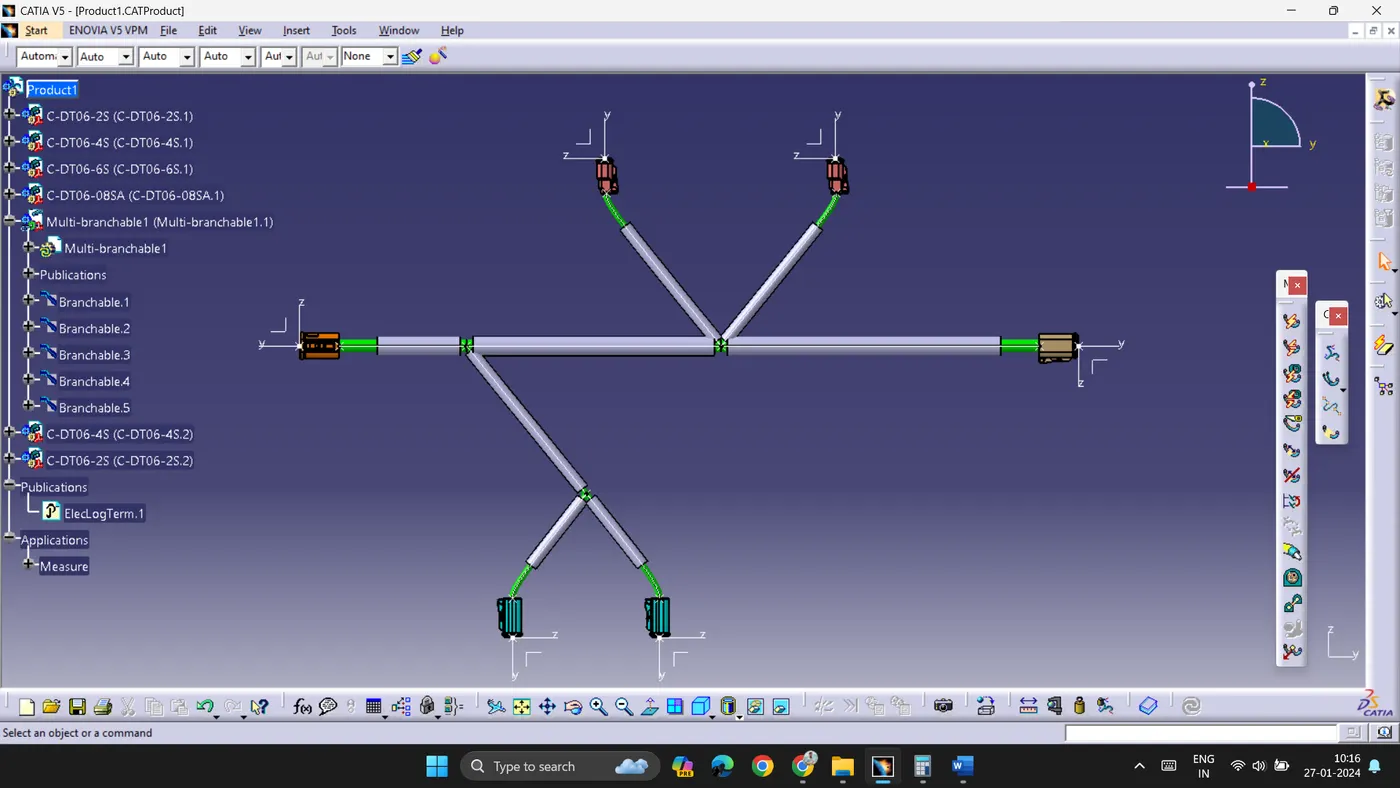
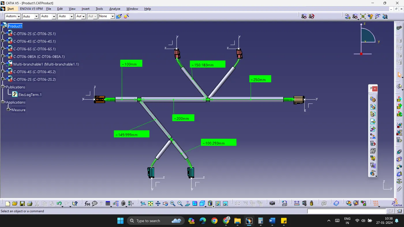
- The extreme point (from connector end) is given 30mm clearance and the junctions are given 5mm clearance to tape the corrugated tubes with wiring harness branch.