Wiring harness design in CATIA V5 - 3D modeling Week 4 Challenge
AIM:
Route the following harness layout in Electrical workbench. Make assumption for harness bundle diameters. Use Following connectors as shown in layout diagram.
Add protective covering on all branches connected to DT06-2S & DT06-4S connectors. Keep end extremity at 30mm (from connectors end)
Download connector 3D data from www.te.com
- DT06-4S
- DT06-6S
- DT06-2S
- DT06-08SA
Master section:
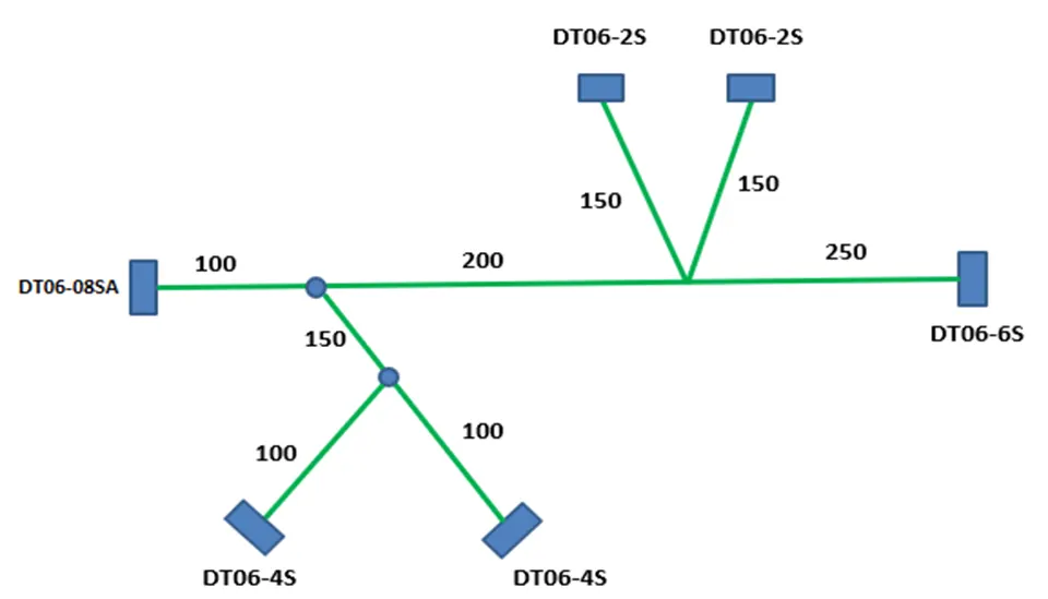
The above given connectors have to arrange as below format and create the harness bundles connecting them.
Procedure for define connectors as a electrical equipment:
· Download the cad files from given link above mentioned and open in the Catia v5
· Define the geometrical properties in the part work bench like points and axis system
· Now switched into the electrical part design to define it as electrical connector
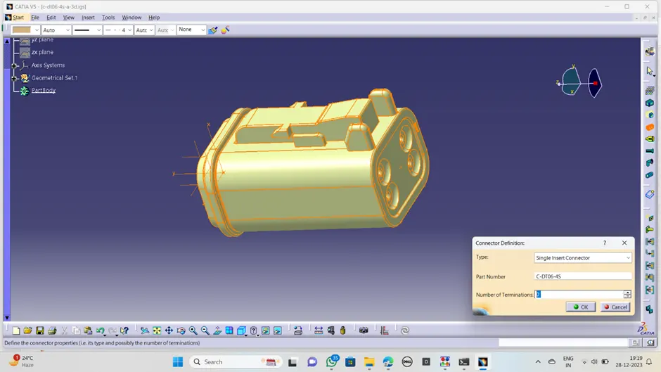
· Click on define connector and click on connector, give appropriate terminals presented to it
· Click on bundle connection point to create the bundle connection point in the bundle entry side by choosing appropriate face and point.
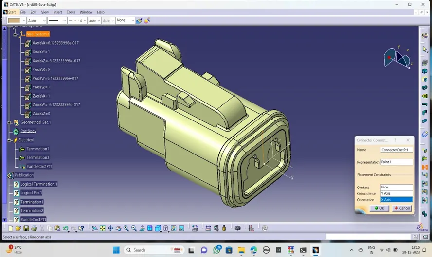
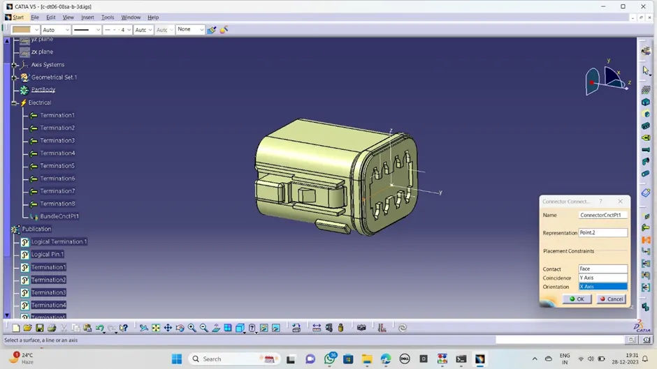
· Click on connector connection point to create the connector connection point connector fixing side by selecting the coincidence, point, rotation and contact.
· Now the connector is becoming the electrical component to use in wiring harness.
· Procedure is same for all above-mentioned connector.
DT06-2S
DT06-4S
DT06-08SA
DT06-6S
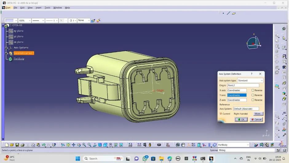
Now all needed connectors defined as electrically and it now readily available to use in harness assembly. For that first we have to make product assembly of all connector .
Procedure for assembly design:
· Create the new product file and download all available required connector into the product file.
· Arrange the all connectors as given master section in question box by using positioning and manipulation tools available in the assembly design.
· Save it in separate folder with suitable name.
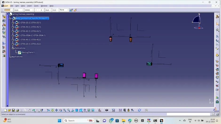
Now switched into the electrical harness assembly work bench to create the bundles between the connectors,
Procedure to electrical harness bundle creation:
· After completing arrangement of all connectors in their respective position,
· Click on the geometrical bundle and click on the assembly ,now the assembly defined electrically
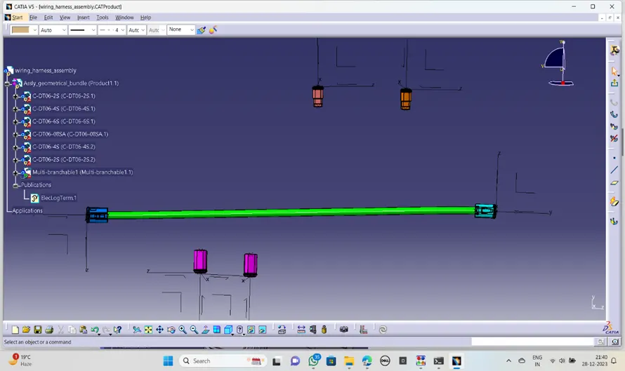
- Click on the multiple blanchable definition and select the diameter of bundle and bend radius, go to the routing definition click connector where we want to create main truck bundle (between DT06-08SA and DTO6-6S).
· Now select the branch point in tool bar and click on the main branch ,create a point at a distance of 100mm.click on branch definition and create a bundle between point and connector as below
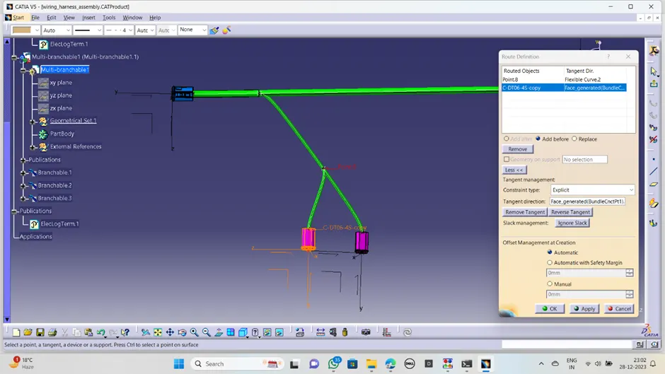
· Again, create another branch point on main bundle at distance of 300mm from starting end. Click on branch definition and create the bundle segment between the branch point and connectors as below.
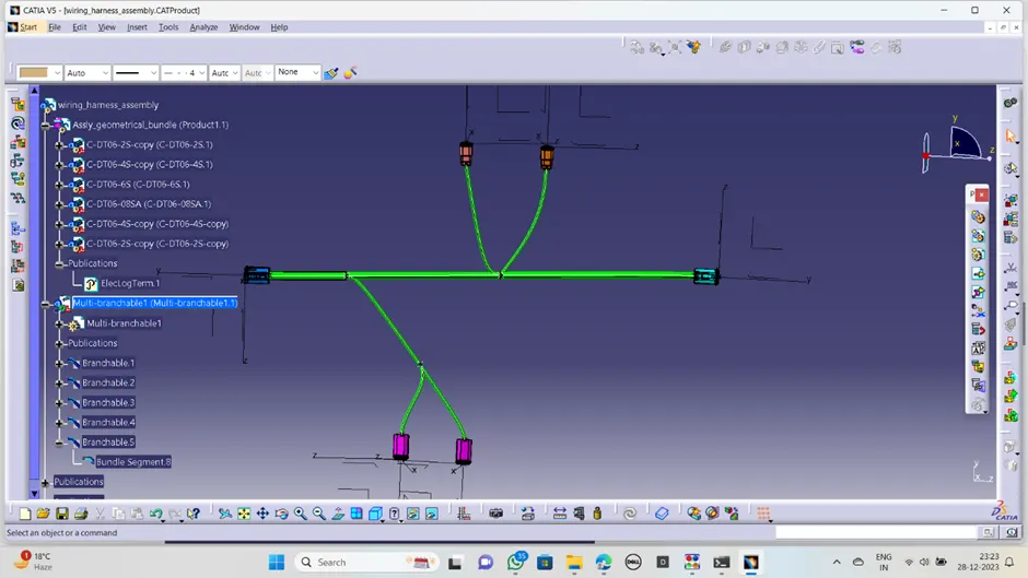
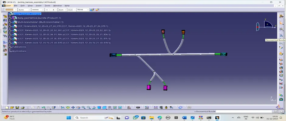
Finaly the harness assembly look like as above mentioned.
Procedure to protective covering:
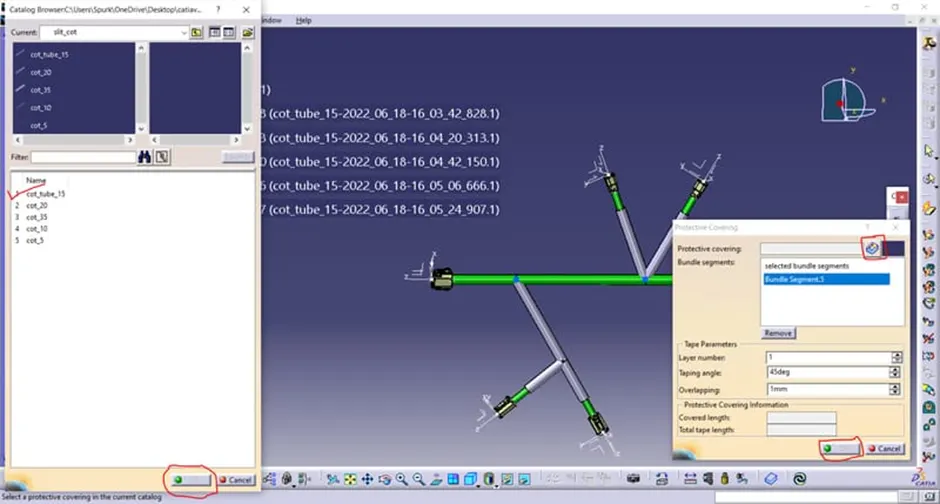
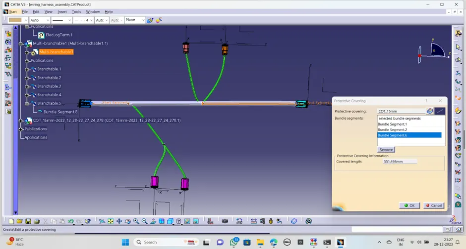
Click on the protect covering in the same work bench, click on the bundle where we want to create protect covering ,select the cot tube from catalogue appropriate dimensions.
· Click on apply then we get the covering around the bundle as below :
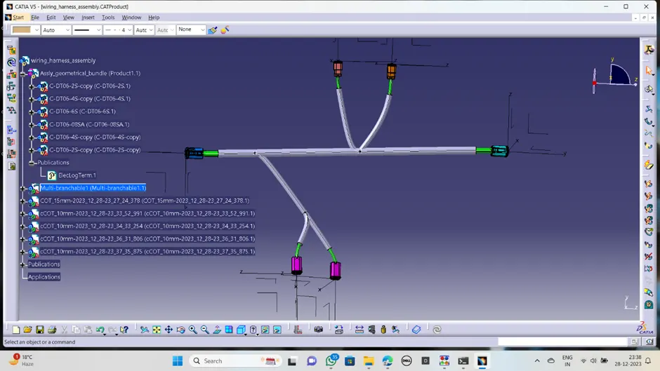
Conclusion:
In this challenge done the wiring harness assembly from the given connector ,created the bundles and applied the protective coverings on the bundles.