Wiring harness design in CATIA V5 - 3D modeling Week 4 Challenge
Solution
Objective
Directing the wiring harness layout in the electrical workbench according to the schematic. Add protective covering to all branches and maintain 30mm end extremities.
Steps
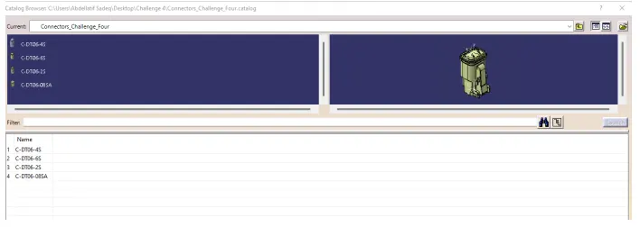
Identify the parts as connector first and define the connection points for each connector as well as the bundle connection points. Then store all the electrically defined connectors in the catalogue, and the command "store device" does that.
DT06-4S
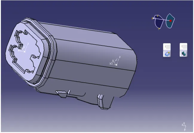
DT06-6S
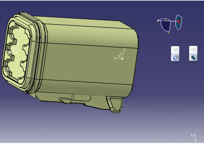
DT06-2S
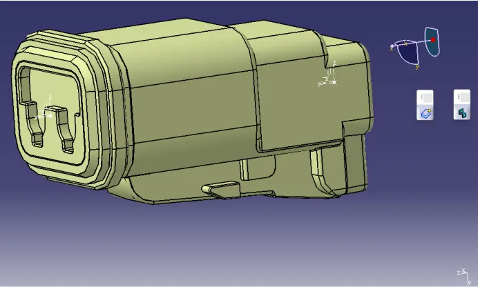
DT06-08SA
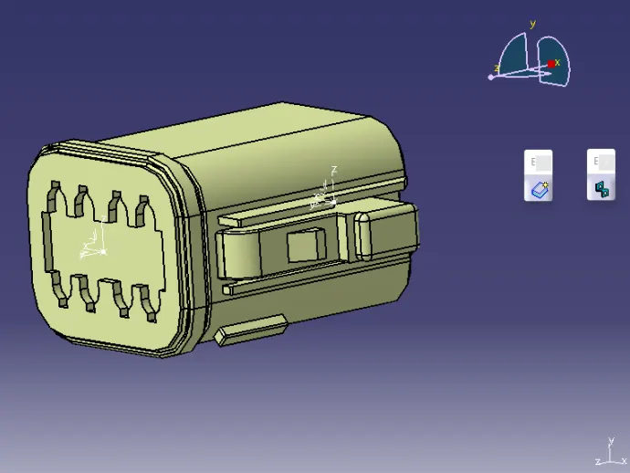
Wiring Harness Creation
1) Select File, then New, then product.
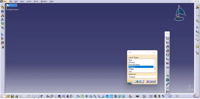
2) Rename the product file (if desired).
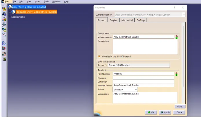
4) Add all the connectors to the "Mechanical Assembly Workbench" from the catalogue
Switch to “Mechanical Assembly Workbench " and use commands such as snap, move, translation, and rotation to adjust the connector according to the distance, where we have to put the connector with the aid of a compass, as well.
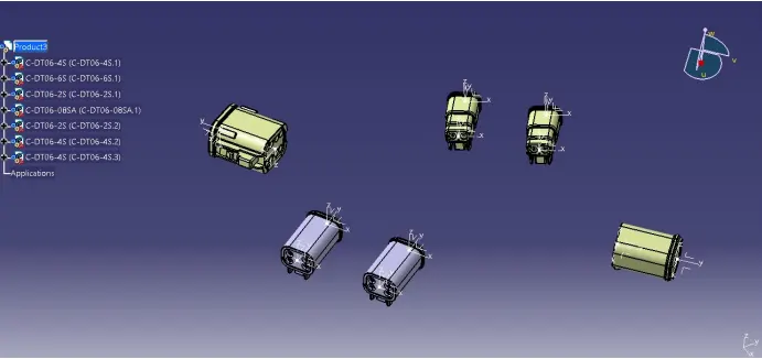
Adjust the distance between connectors as requested in the space using the compass and snapping features. After that, Switch to the “Electrical Harness Assembly" workbench. Click on Product3 (this name is only used for this example and not generic), and define it to be electrical using the command.
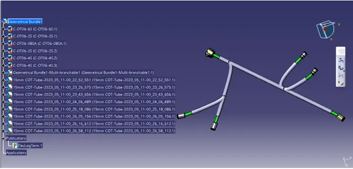
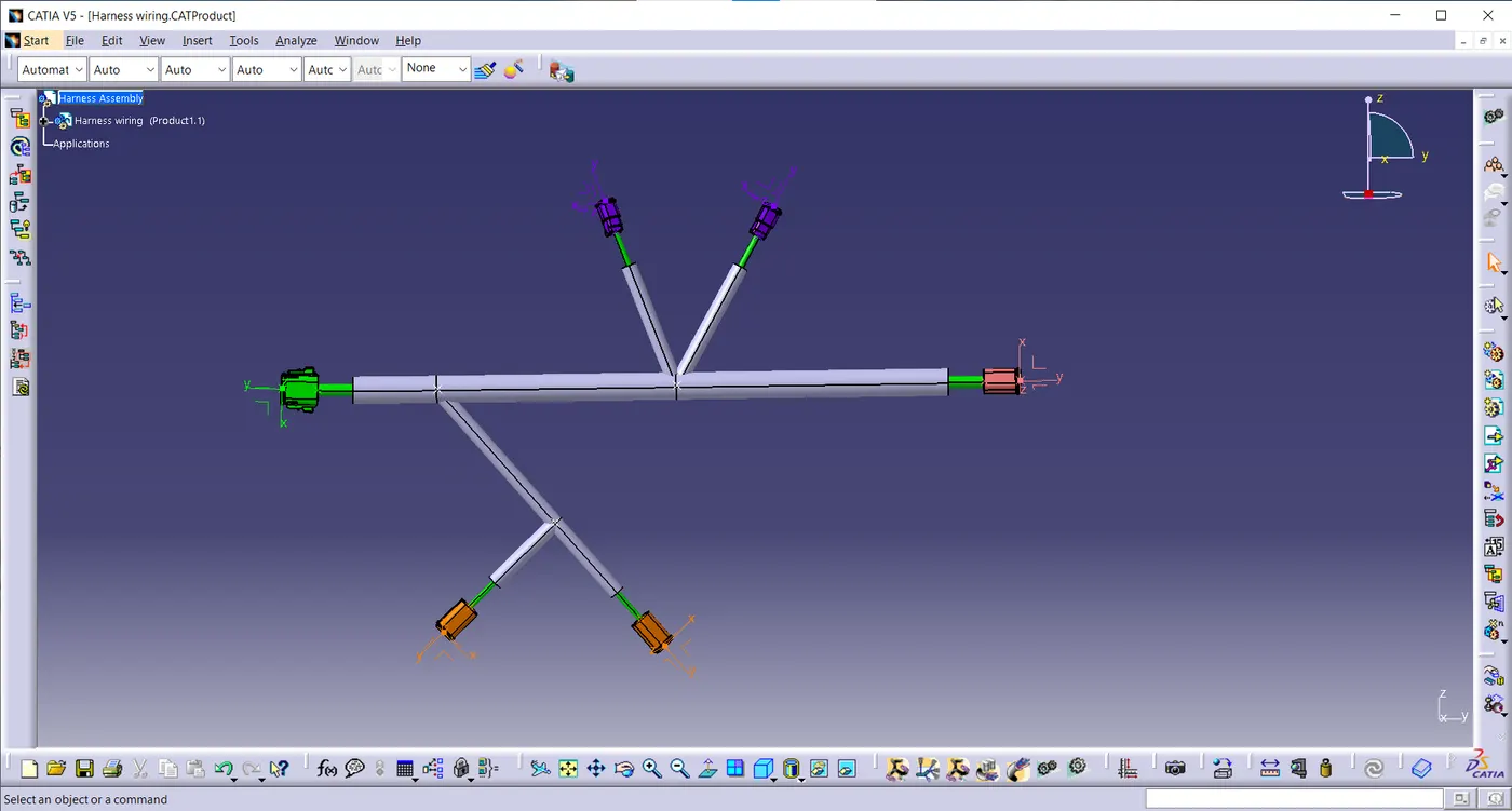
“Geometrical Bundle”. After that, start routing the bundles between the connectors using “Branch Definition Command” after adding the “Multi Branchable Document”, in addition to adding the branch points at the desired locations. The assembly after routing should look similar to the below one.
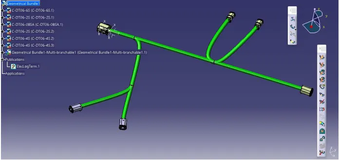
Add the protective coverings to the bundles, and keep an end extremity of 30mm for all branches, as below.