Wiring harness design in CATIA V5 - 3D modeling Week 4 Challenge
Q1. Route the following harness layout in Electrical workbench. Make assumption for harness bundle diameters. Use Following connectors as shown in layout diagram.
Add protective covering on all branches connected to DT06-2S & DT06-4S connectors. Keep end extremity at 30mm (from connectors end)
Download connector 3D data from www.te.com
- DT06-4S
- DT06-6S
- DT06-2S
- DT06-08SA
The above Connectors are downloaded .
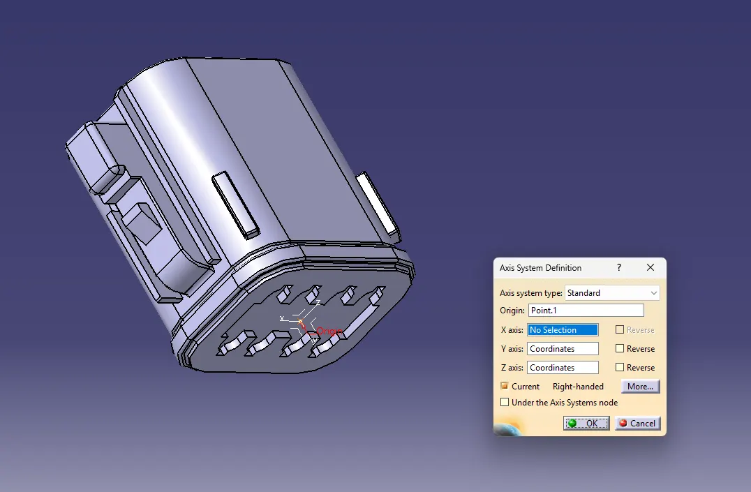
Define the middle point and the axis definition system for every part downloaded.
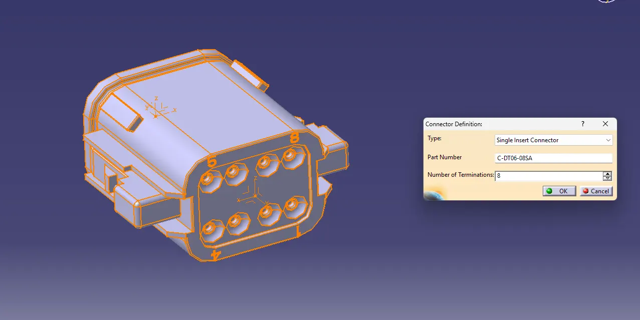
Define the part as connector.
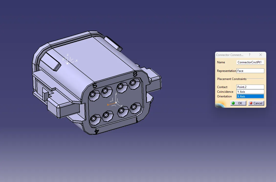
Define the connector connection point where y direction will be facing towards mating.
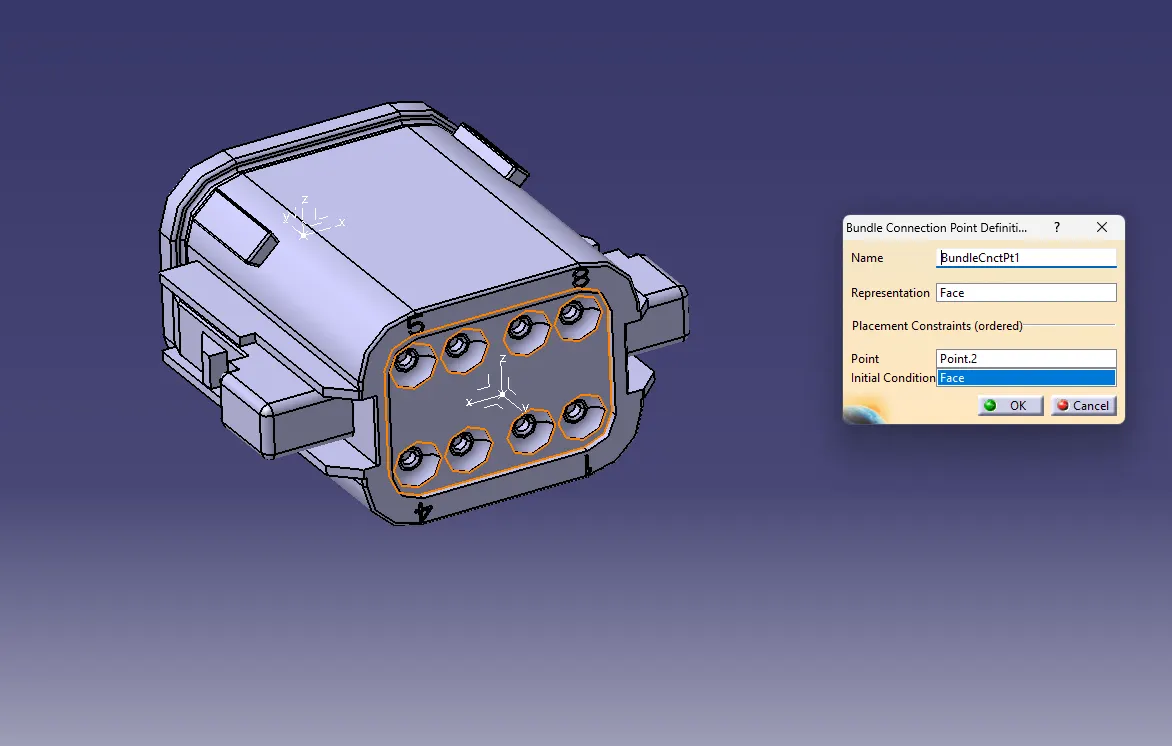
Define the Bundle connection point.
Proceed the same step with all Downloaded parts similarly.
For the location of Branch Point and connector distance , create a sketch profile of the connector location in the workbench and then insert it into the Harness Assembly Design.
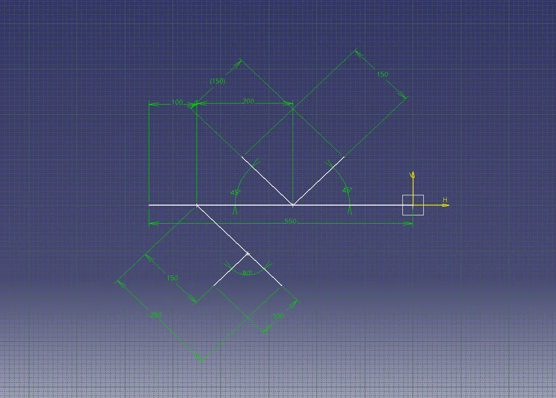
Here the angle is taken randomly based on the figure provided.
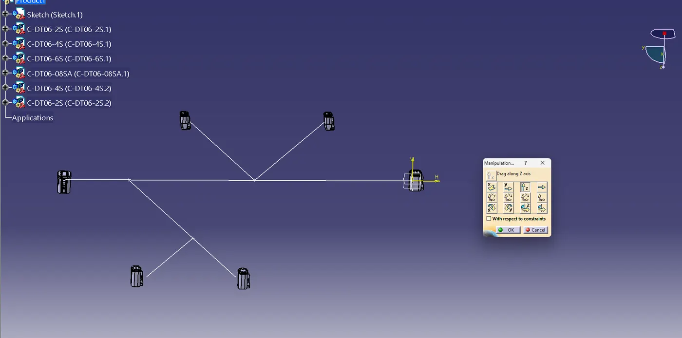
Insert all the Connectors and the sketch in the Harness Assembly Design.
By using Manipulation tool placed the connectors on their respective location.
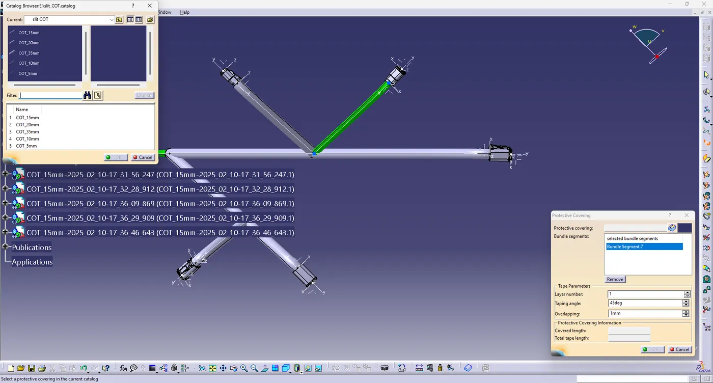
Make the Product as Geometry Bundle defined and proceed with mutiple Branchable define .
provide protection covering on each Branchable wiring harness design.
using the catalogue browser a 15 mm covering is installed as our wiring harness was of 10mm.
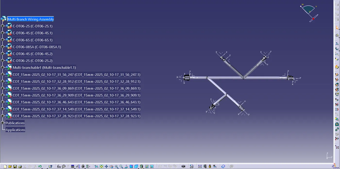
Protection Covering of wiring harness design. but there's a 30 mm exremity from the connectors end.
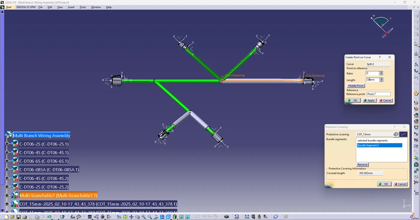
A 30 mm extremity is provided on the connector side .
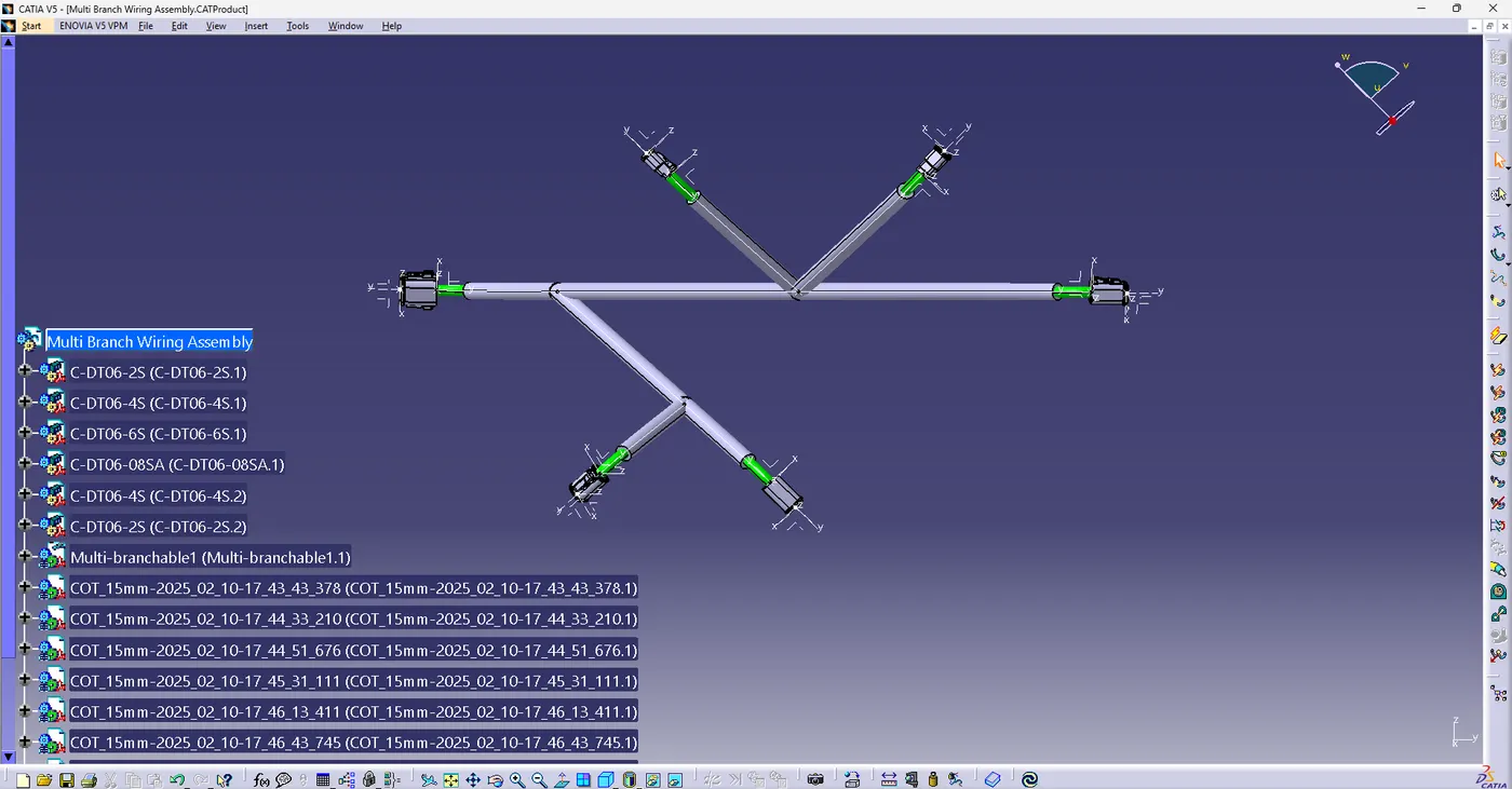
The final Product after giving extremity on all the branches.