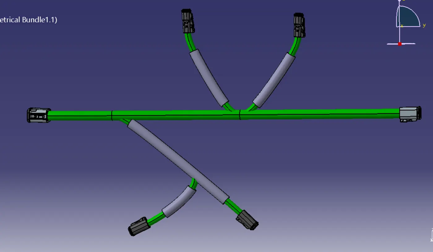
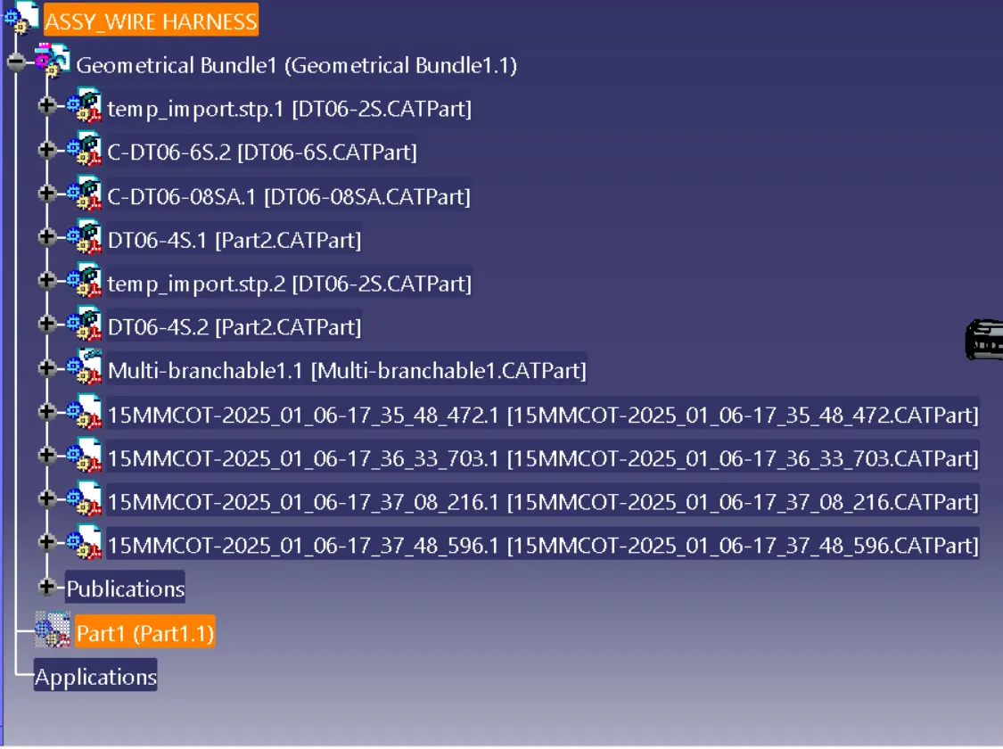
Wiring harness design in CATIA V5 - 3D modeling Week 4 Challenge
WIRE HARENESS DESIGN
Connectors:
1. Create or Import the Connector Geometry
1. Design the Connector:
o Use the Part Design or Generative Shape Design workbench to model the connector.
o Ensure the geometry includes features like pins, mounting holes, and bundle entry points.
2. Import an Existing Model:
o If you already have a CAD file, import the connector geometry into CATIA.
2. Switch to Electrical Part Design
- Go to Start > Equipment & Systems > Electrical Part Design.
3. Define the Connector as an Electrical Component
1. Select Define Connector:
o In the Electrical Part Design toolbar, click Define Connector.
2. Assign Properties:
o Assign a name and other metadata to the connector for identification.
4. Define Connection Points
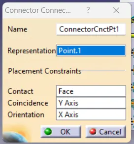
1. Create Connector Connection Points:
o Select Define Connector Connection Point.
o Click on the connector pin or face where the electrical connection will be made.
o Specify:
§ Direction: Define the orientation of the connection.
Type: Choose the type of connection
1. Create Cavity Connection Points (Optional):
o Use Define Cavity Connection Point for connectors with cavities.
o Specify the location and orientation of the cavity point.
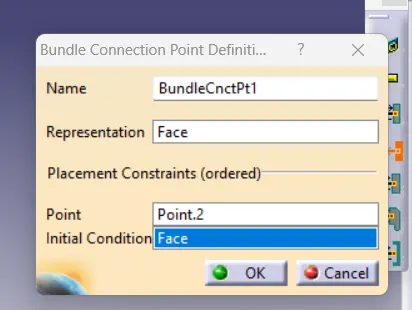
5. Define the Bundle Entry Point
- Select Define Bundle Connection Point.
- Click on the surface or edge where the wiring bundle will enter the connector.
- Specify:
- Direction: Ensure it aligns with the intended cable routing.
- Diameter: Define the maximum bundle diameter.
Bundle creation:
1. Prepare the Environment
1. Set Up the Workbench:
o Open the Electrical Harness Installation workbench.
o Ensure all required components, such as connectors, backshells, and mounting equipment, are correctly defined and available.
2. Insert Components:
o Add connectors, clamps, and other components to your assembly using the Electrical Harness Assembly workbench.
2. Create a New Harness
1. Create a Multi-Branchable Document:
o Click Harness Document from the toolbar to create a new document for your harness.
2. Define the Bundle Context:
o Add connectors and components to the harness assembly.
3. Define Bundle Segments
1. Select the Bundle Segment Tool:
o In the Electrical Harness Installation workbench, click Bundle Segment.
2. Specify Bundle Routing:
o Pick Routing Points:
§ Select points (bundle entry points on connectors) to define the path of the bundle segment.
o Define Geometry:
§ Use 3D geometry (planes, lines, or edges) to guide the bundle routing.
3. Define Properties:
o Set the bundle segment properties:
§ Diameter: Specify the bundle's diameter.
§ Material: Choose the insulation material.
§ Bend Radius: Ensure the bundle meets minimum bend radius requirements.
4. Validate the Segment:
o Check the bundle's path and ensure it avoids interferences with other components.
4. Add Branch Points
1. Insert Branch Points:
o Use the Branch Point tool to split or merge bundle segments.
o Select a point along the existing bundle segment where the branch will originate.
2. Route Additional Segments:
o Create new segments from the branch point to connect additional components.
5. Add Protective Covering
1. Define Protection:
o Use the Protection tool to add coverings such as sleeves or conduits.
o Specify the material and length of the protection.
DESIGN VIEWS: