Wiring harness design in CATIA V5 - 3D modeling Week 4 Challenge
Aim:
1) To Route the following harness layout in the Electrical workbench.
2) Add protective covering on all branches connected to DT06-2S & DT06-4S connectors.
Given:
CAD data of the following Connectors:
- DT06-4S
- DT06-6S
- DT06-2S
- DT06-08SA
Connectors Layout Design:
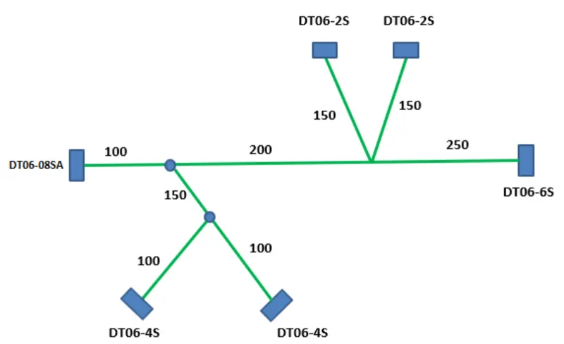
Steps to be followed:
1. Download connector 3D data from www.te.com
- DT06-4S
- DT06-6S
- DT06-2S
- DT06-08SA
2. Convecting the Mechanical part into the Electrical part for that I had followed the following steps.
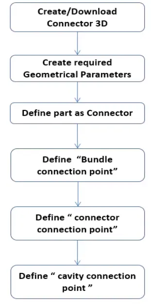
-> 1st downloaded all the given connector and make point & axis in the part design. And dfined the given connector as a electrical component & provid all the respected features to the connector in the electrical part design work bench.
1. DT06-08SA :-
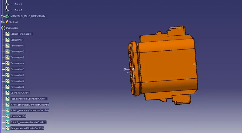
2. DT06-6S :-
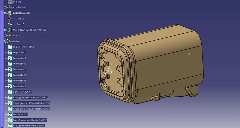
3. DT06-4S :-
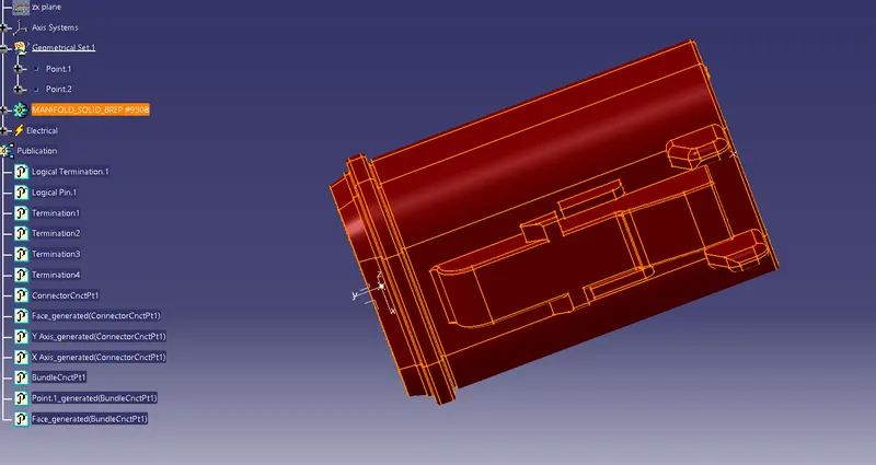
4. DT06-2S :-
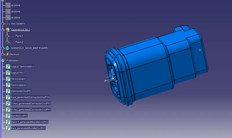
After that I created a product_Context_FIle and created a sub_Prodeuct_file named as Assy_Geomatrical_Bundle in the main product file.
And switch the Assy_geomatrical_bundle file and uploaded all the 4 connectors and make it in the orientation as defined in the drawing in Assembly design by using compass and manuplate command.
Then go to a new part design the make a sketch as per given drawing.
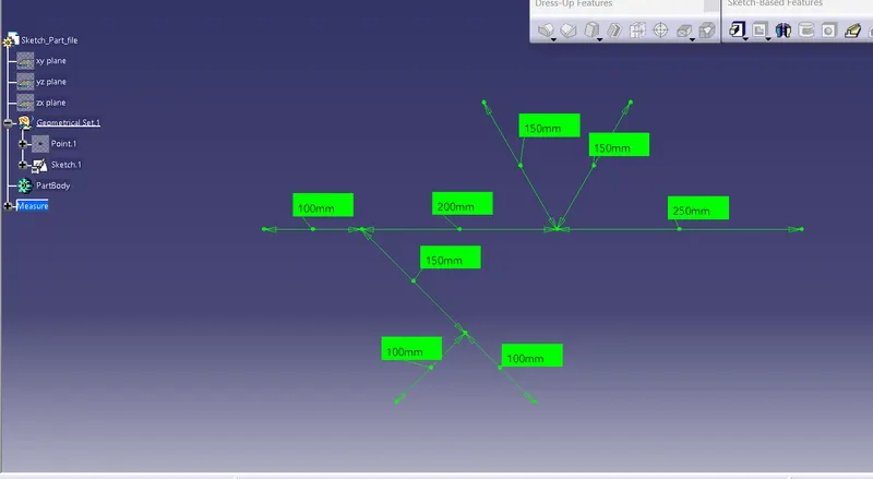
Then again switch to assembly design and fix all the connectors at the line end with the help of Snap command.
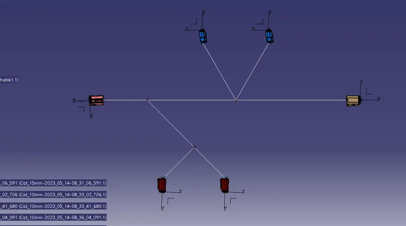
Then switch to Harness assembly design and make the product file as geomatrical bundle to define it as electrical assembly.
Then add multi branches and added branch point to create harness.
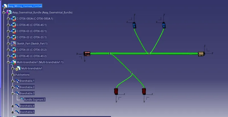
Then I added protected covering to the harness_context and added extrimity point as 30 mm distance to the connector of DT06-4S & DT06-2S at connectors end.
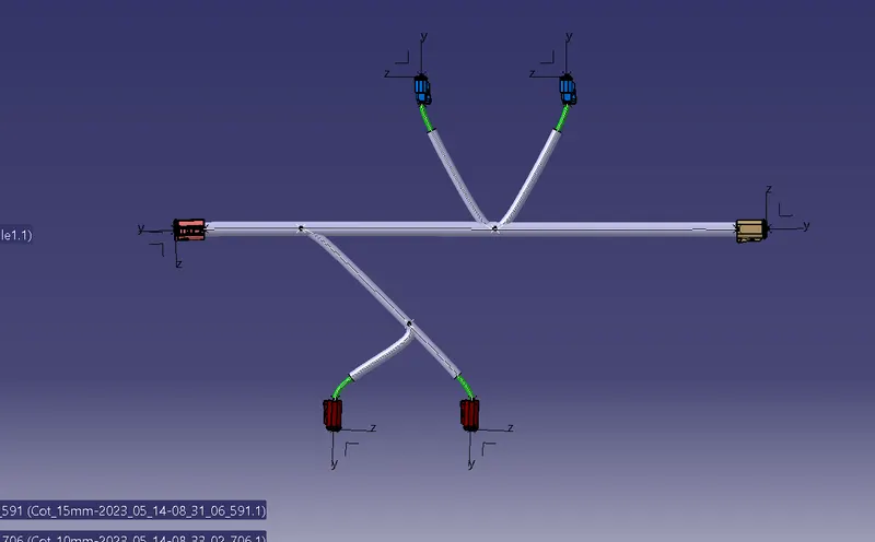
Hence completed my assignment.
Thankyou & Regards
Vivek