Wiring harness design in CATIA V5 - 3D modeling Week 4 Challenge
AIM:
- Download the connector from the given link.
- Load the connector in mechanical part design and given point and axis by using point definition and axis definition.
- Then go to the elecrical part design and define it as a connector.
- Give bundle point and connector connection poinT
-
DT06-2S,DT06-4S,DT06-6S,DT06-08SA.
-
First imported models from given link. open mechanical part design.
- Defined the middle point with help of the mid point. On the connector side and bundle side.
- Given axis system to connector side.
-
Rotated x-axis 90 degrees for y-axis coincidence.
-
Now changing the workbench electrical part design.
- Defined as a connector with 2 terminations.
- Then Defined the connector side as the connector connection point.
- Defined bundle connection side as a bundle connection point.
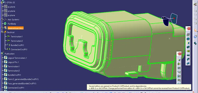
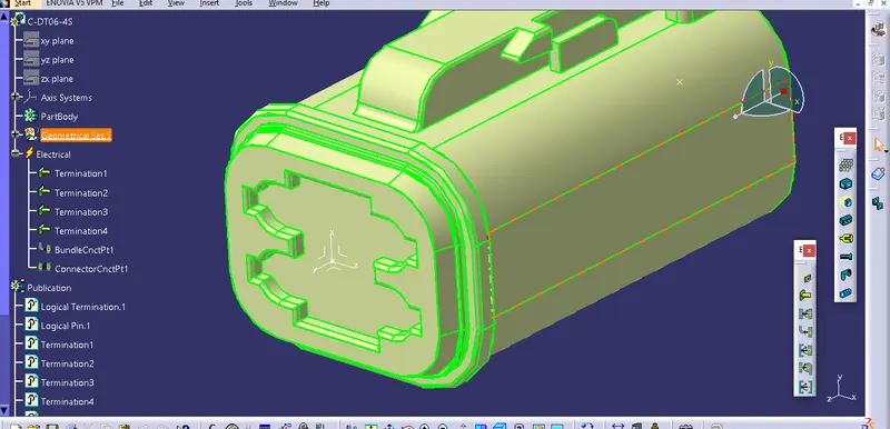
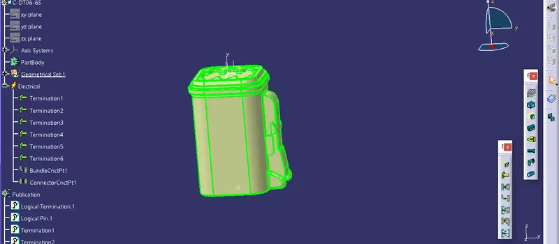
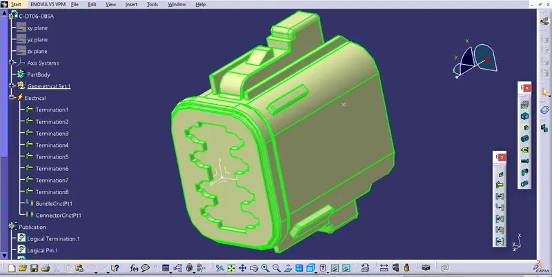
procedure to draw sketch
- Go to the file select new and then select part.
- In the part select any plane and draw the sketch by given mesaurement.
- As shown in the above diagram and save the sketch.
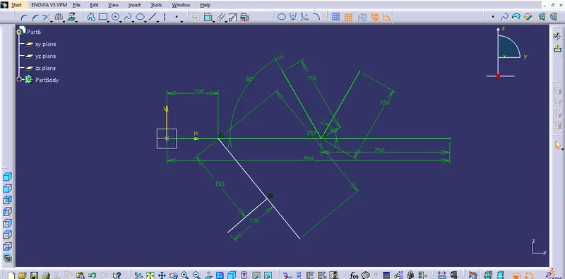
procedure for the elctrical assembly design
- Load all the connector in the elctrical assembly .
- For the manipulation of the connector go to the mechanical assembly design.
- Use the tool manipulation for the proper and required arrangement for the connector.
- The black marking is use for the manipulation tool and red marking is use for the snap tool.
- These are the both tool used for the rearrangment of the parts.
- After doing arrangment go to electrical harness assembly for harness bundle connection.
- In this process the harness is connected to the connector.
- First go to the geometric bundle tool select on that then select on the part name on the tree .
- Now the part is electricaly defined.
- Now go to the bundle segment then select the route definition.
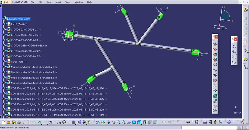
Made Cot for all sub-branches by maintaining a 30mm distance from the connector side.
Completed the challenge.