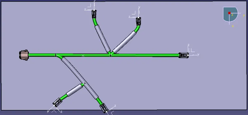
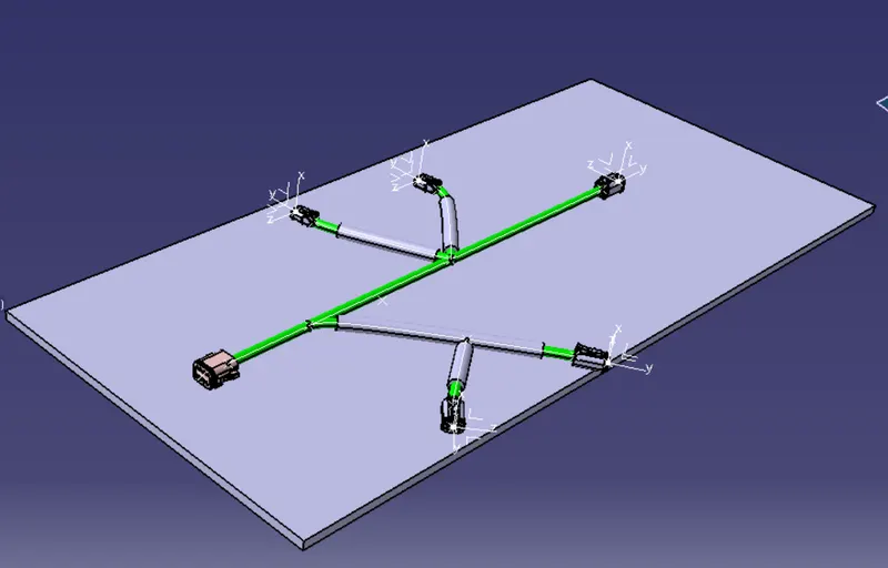
Wiring harness design in CATIA V5 - 3D modeling Week 4 Challenge
Step 1:
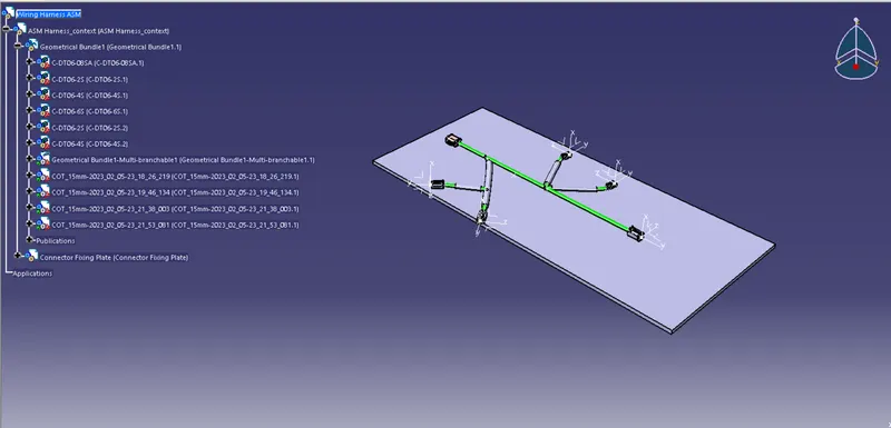
Create a product file for Wiring harness and create a geomentric bundle asm inside the wiring harness ASM.
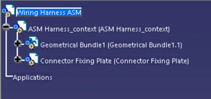
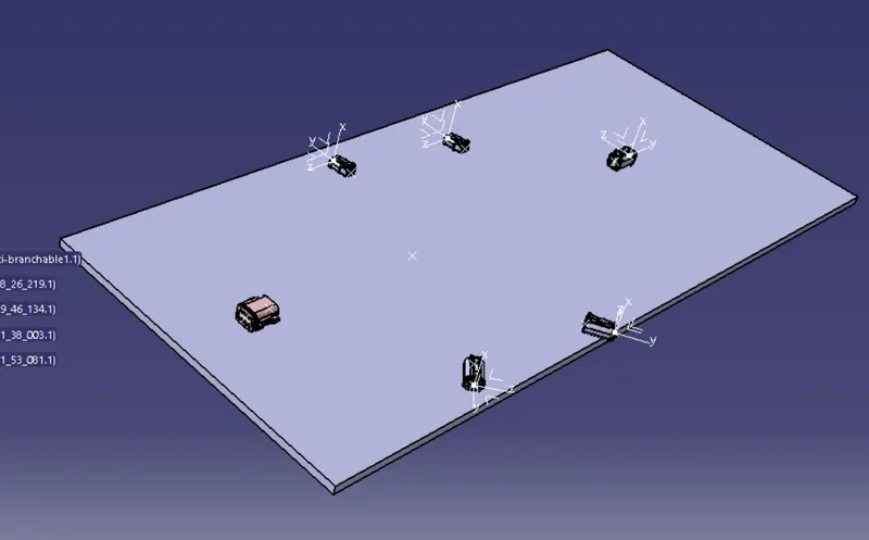
A Fixing plate is created in another product file to place the connectors over the plate.
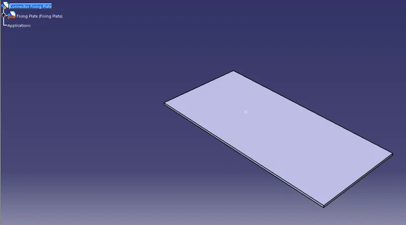
Step 2:
Define the Connectors in the Electrical part design and define the connector connection point and bundle connecction point.
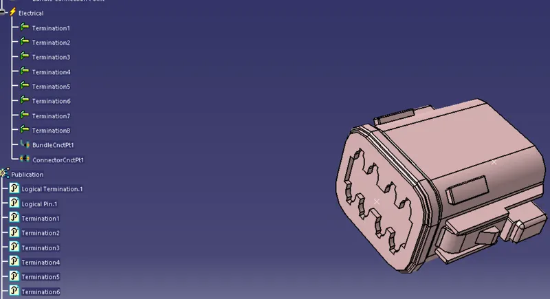
Step 3:
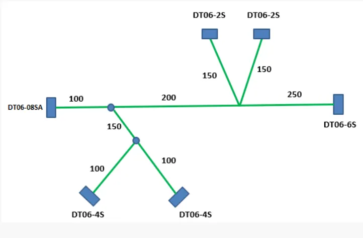
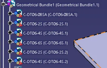
i)Insert the electrically defined connectors in the geomentric bundle and place the connectors according to the given diagram. Make sure all the connectors are electrically defined before insering into the assmbly.
ii) Define the geomentric bundle assembly as Geomentric bundle by clicking on the icon shown below. Now the Geomentric bundle ASM icon changes to electrical harness asm.

Step 4:
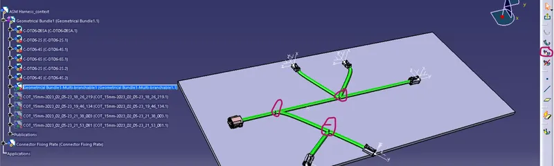
Click on Multi branchable icon in ELectrical harness asm workbench. This will create branches connecting the connectors. Create each branch individually for 2 connecting points.

For branch points, Click the branch point icon and select the branch where we have to split the branches andm enter the value as specified in the diagram. This will create multiple branches branching out from a single branch.
Step 5;
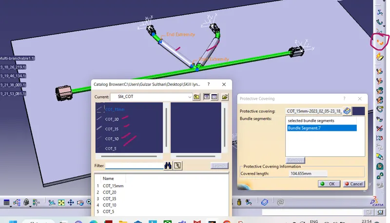
To add Protection coverings Click the protective cover icon and select the branches which needs protection. Protective coverings are created and stored inside a catalogue file. Covering of specific size can be picked and can be used in the assembly.
Final Harness ASM: