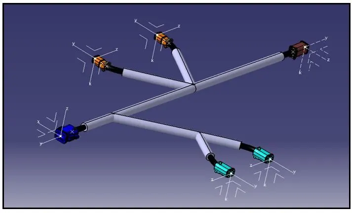
Wiring harness design in CATIA V5 - 3D modeling Week 4 Challenge
Defining of connectors from mechanical part to electrical part
The Connectors to be defined electrically are to be created or 3D part file is to be downloaded from the respective websites.
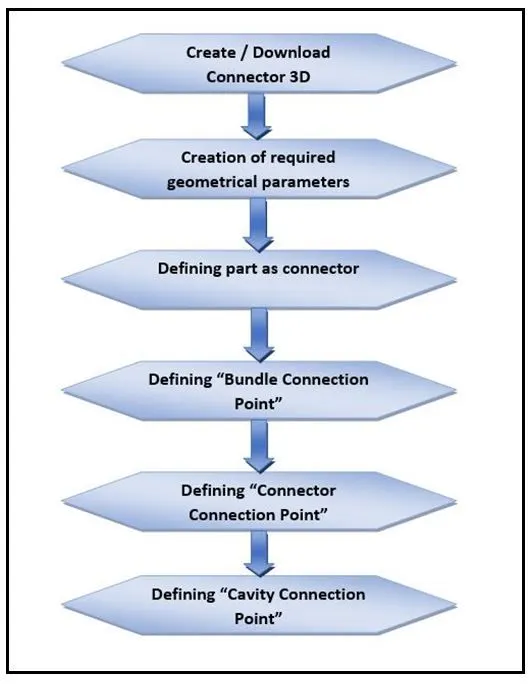
The process for connector definition in CATIA is shown below,
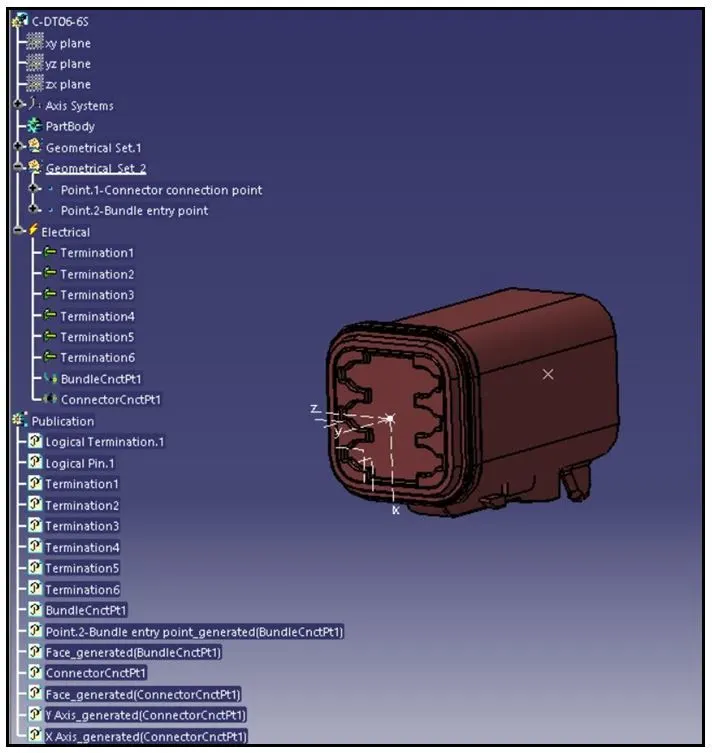
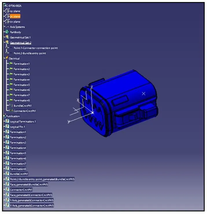
The connectors which are defined electrically is shown below,
- DT06-2S Connector
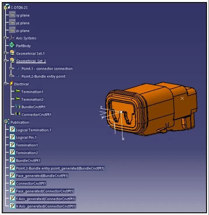
- DT06-4S Connector
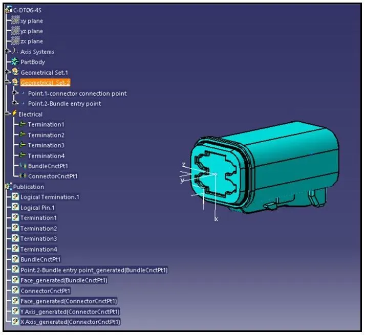
- DT06-6S Connector
- DT06-08SA Connector
Bundle Routing of connectors in electrical harness assembly workbench.
- Preparation of harness assembly
The Wiring harness product assembly contains the following components,
- The harness context assembly.
- Geometrical Bundle.
- Electrical Bundle.
- The harness context assembly: -
The Harness context assembly is the top-level product file that contains the harness geometrical bundle and the wire harness electrical bundle.
- Geometrical Bundle: -
Geometrical bundle is the sub level product which contains all of the harness components. i.e., clips, supports, splices, grommets, annotation and actual physical bundle segments and branches.
- Electrical Bundle: -
Electrical Bundle is a sub-product file, which contains all of the electrical circuit information.
Defining of the wire harness routing.
Conditions to be adhered for wiring harness routing is shown below,
- Geometrical Bundle assembly is to be completed.
- All components are placed at desired locations.
- All type of electrical connections/constraints are defined.
- Background Geometry Data is available and assembled in Geometrical bundle context assembly.
- All clips / clamps /channels are placed at desired locations.
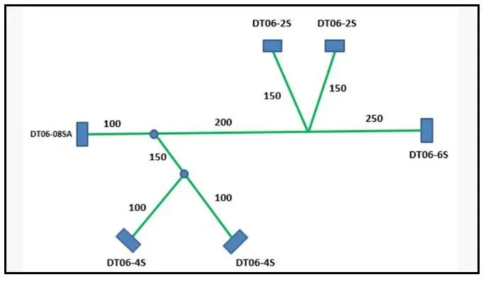
The preparation of bundle routing for the connectors, which are electrically defined is to be done as per the electrical circuit drawing provided below,
The electrical defined connectors assembled in electrical harness assembly workbench is shown below,
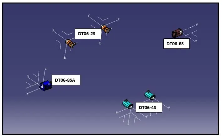
The assembly of the electrical defined connectors is made under the sub-assembly – product named “geometrical Bundle assembly”
The bundle routing is initiated as per the electrical circuit drawing shown above.
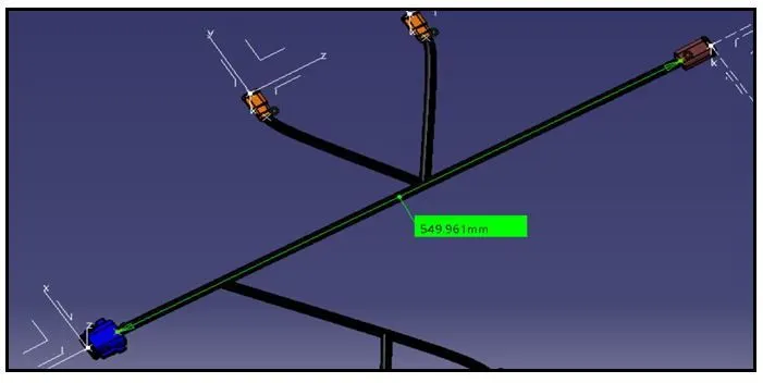
Firstly, the bundle routing is done for connectors DT06-6S and DT06-8SA as shown below,
Next, the Bundle routing is done for connector DT06-2S of two numbers with the newly added branch point in the main trunk/main branch shown below,
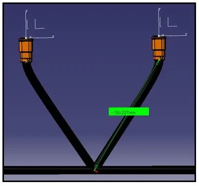
The addition of branch point in the main trunk helps in creating a multi-branch using “branch definition” command.
In the Similar way, one more multi-branch is created for routing the bundles with two number of DT06-4S connectors as shown below,
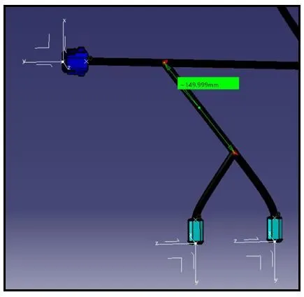
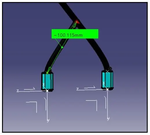
The Final bundle routing to all the connectors as per the provided electrical circuit diagram is shown below,
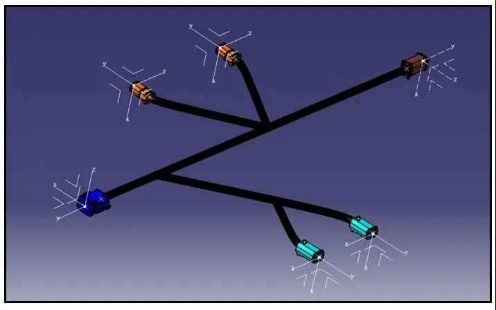
Addition of protective coverings on the electrically routed bundle.
The protective coverings are added on the created bundle segments, by using protective covering command in ‘Electrical Harness assembly” workbench.
The type of Protective covering used in bundle segments is CORRUGATED TUBES.
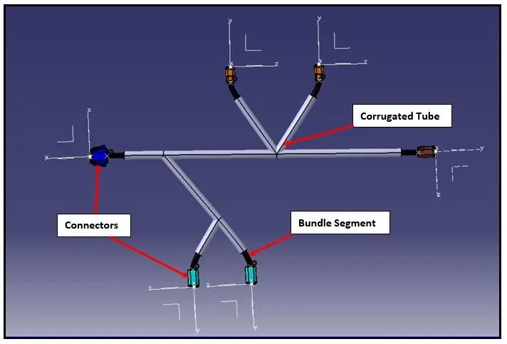
The CORRUGATED TUBE of diameter 15mm is used to provide protective covering on 10mm diameter of bundle segments.
The CORRUGATED TUBE is maintained with an end extremity of 30mm from the bundle entry point of the connector/end point of the connector.