Wiring harness design in CATIA V5 - 3D modeling Week 4 Challenge
1st open connectors (DT06-08SA)into catia v5 and define it as per the mentioned bloe steps .
defining step -1 create point &axis system at center on connector connection point in part desgin workbench & ensure y axis axis normal to face &x axis along the the locking direction.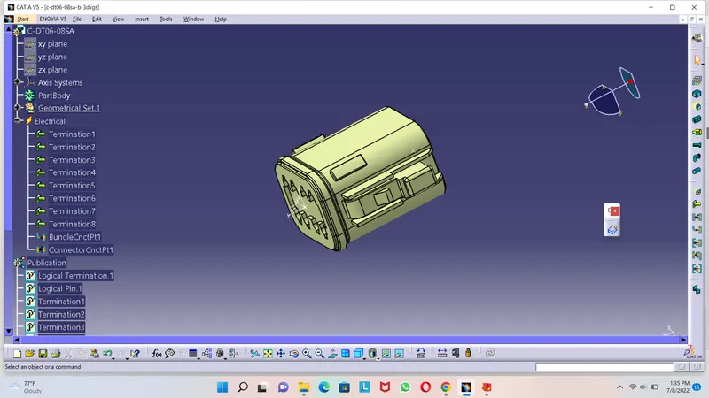
defining step -2 create point at center on bundle connection side .
defining step 3 swith into eletrical part desgin workbench and define it as eletrical component by using define connector command & click on part ,give input 8 in dialogue box for number of termination as this connector has total 8 termination points ,then click ok.
defining step 4 use define connector connection point command and select input.
step 5 use define bundile connection point command and select input.
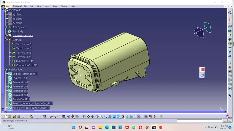
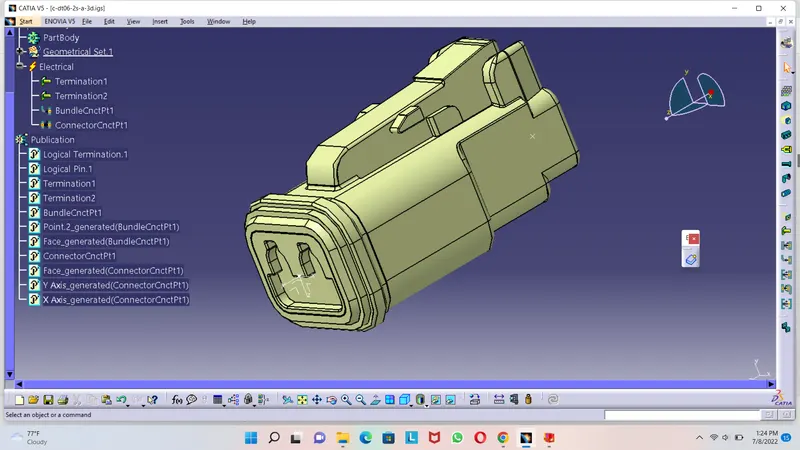
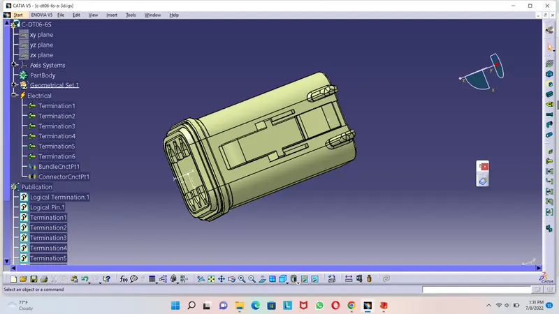
follow above some steps to define other connectors &give respective termination points 4 6 &2 while defining connectors for DT06-4S,DT06-6S,DT06-2S
now to route wiring to the connectors ,call all the defined connectors into normal assembily desgin workbench &arrange these connectors as per given layout with manipulators or axis system .
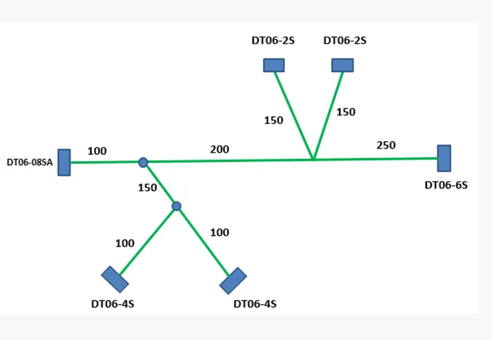
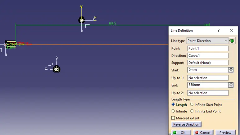
create line as shown in image below and end of line will be at 550mm from origin ,then with snip tool arrange connector (C-DT06-6S)at this end of line as per layout
angle assumed for branches and layout diagram constructed with point ,line &axis system
now arrange all connectors at specified location by manipulation and snap command
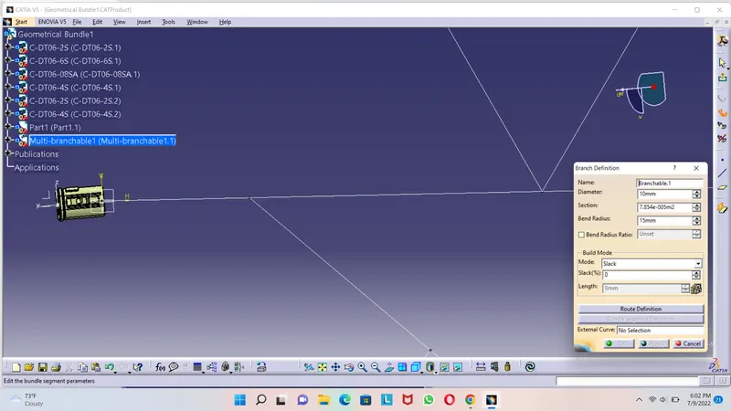
now switch into eletrical harness assembily assembly & with geometrical bundle command convert normal assembly into eletrical assembly ,then click on multi branch abile document give highligted inputs as shown in image (diameter &bend ,radius ratio )get into route definition and select these two connectors as shown in image below .
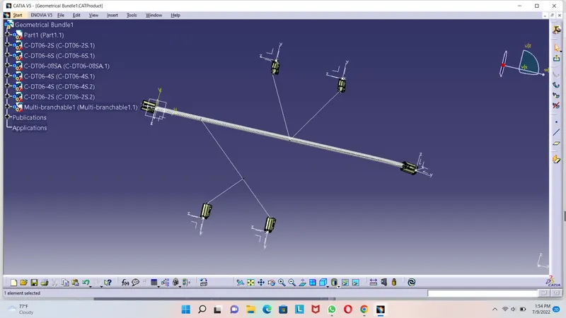
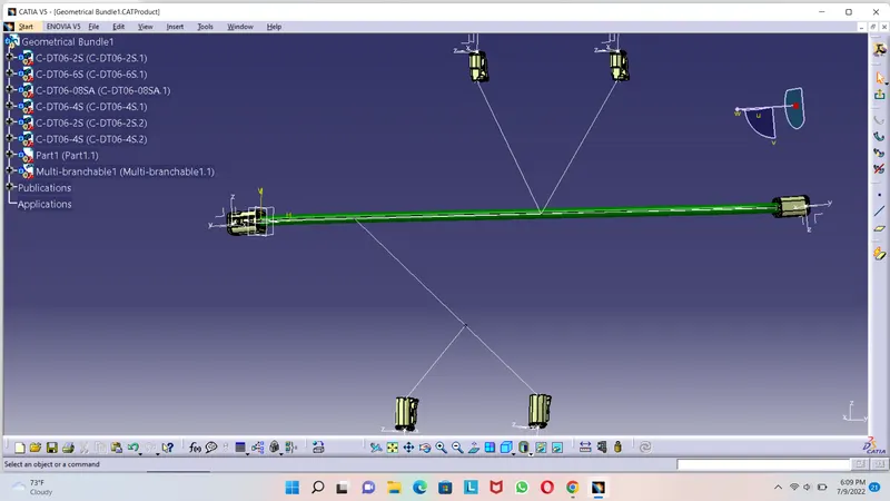
then with branch defintion add branch
then with branch defintion command in route defintion add remaining branhes
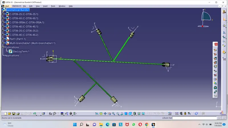
tq