Wiring harness design in CATIA V5 - 3D modeling Week 2 Challlenge
Define the Electrical Connector using Electrical Part design Workbench with all the necessary properties to Connectors & Clip
Aim – Define given connectors and connector clip as an Electrical Connector and add their necessary properties using Electrical Part Design workbench on Catia V5.
Objective -Download the File From TE.com Then define as an electrical connector or equipment and Give all the required electrical properties to them using the electrical part design workbench on Catia V5.
Required steps for Design the Project
Create/ Download Connector 3D
Create required Geometrical Parameters
Define Part as a Connector
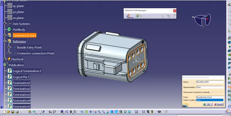
Define Bundle Connection Point
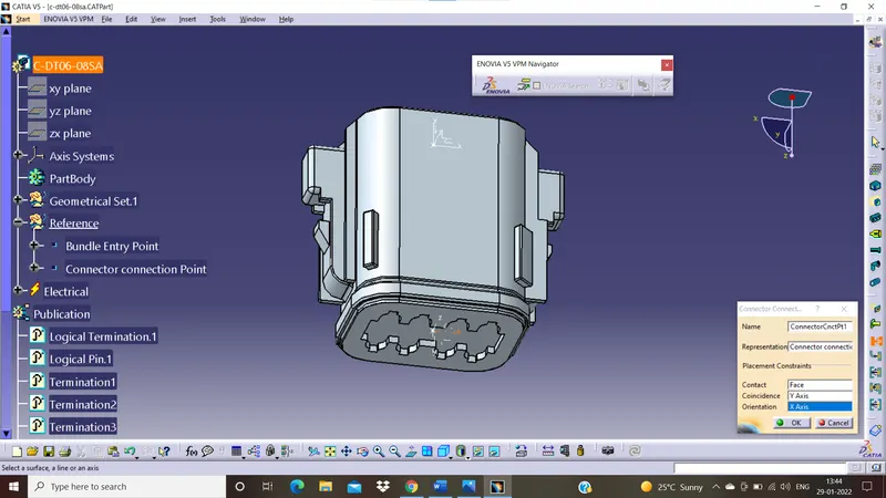
Define Connector Connection Point
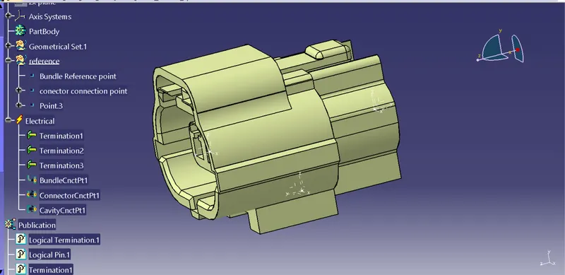
Define Cavity connection Point ( If there is a clip)
Geometry Parameters – Points and Co-ordinate Axis
Connector connection points – This point is used for the connection of one connector to another connector.
Harnes Bundle Entry point – This point define where the harness bundle segment point will end when routed to the electrical connector.
Cavity connection point – Point is used to define the connection of a connector to a connector clip. This only applies to connectors which have the mounting feature for a connector clip.
Connector Definition In Catia V5
Connector Deutsch DT06 – 08SA
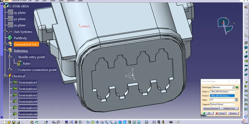
Creating connecter to connector point
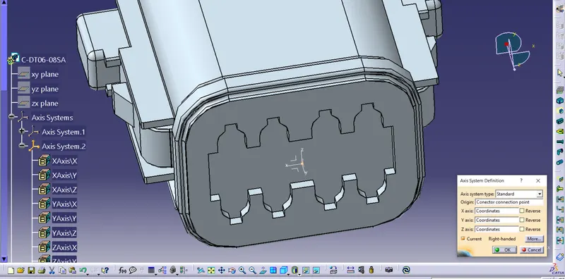
Now that you have created the axis on 0.0.0 we must move the connector so that the center 0 the front face of the connector is on 0.0.0 we will create a point as the contact when making connector to connector connections
The connector axis system should be on the front face of the connector attached to a point on 0.0.0 co-ordinator to another electrical component.
Switch to ‘Electrical Part Design’
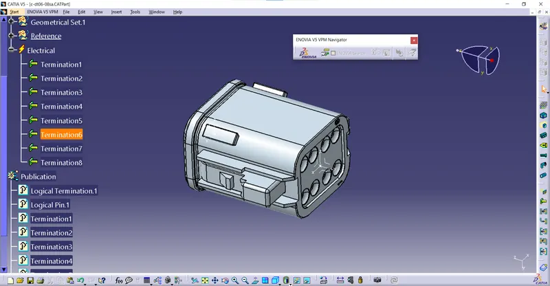
Define the part as connector in catia, giv ethe number of terminals as 8 because we have 8 entry points for Bundle
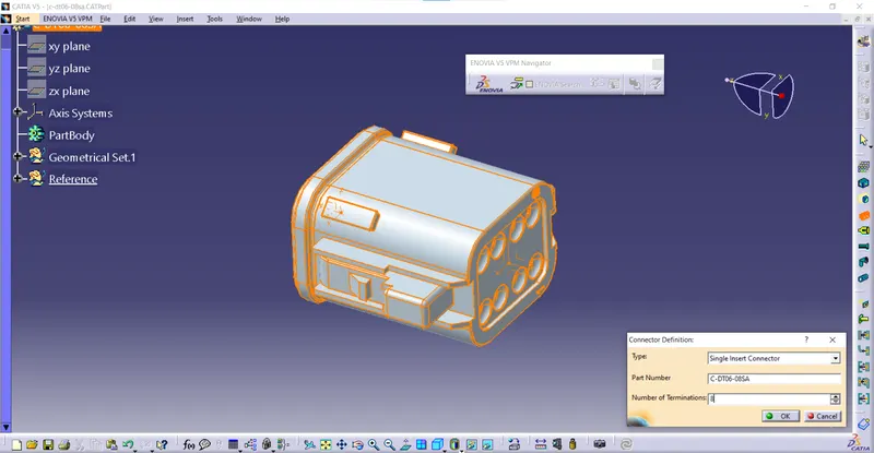
Define Bundle connection point -
Define the conector connection point -
Connector Tyco 174357-2
Clip Tyco 85229-1
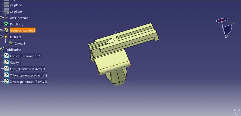
In case of connector cavity definition we had used connector cavity connection point used for cavity connector were as in case of clip we need to use the Define cavity because mating side should be as an cavity so the software as read the cavity connection part
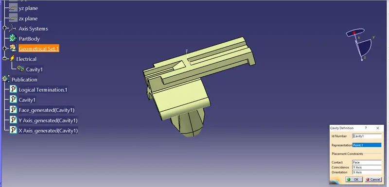
Electrical Assembly Design
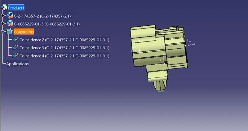
Part Design - import connector and clip adjest the both by using Manupulation command - Electrical Assembly Design - Electrical connector
Import connector and cavity clip
Select Defining Electric connection
Select Cavity and then connector