Wiring harness design in CATIA V5 - 3D modeling Week 2 Challenge
Wiring harness design in CATIA V5 - 3D modeling
Aim:
Given 3D models are defined as electrical connectors using Electrical Part Design Workbench. Also defining all the necessary properties to Connectors and Mounting clips.
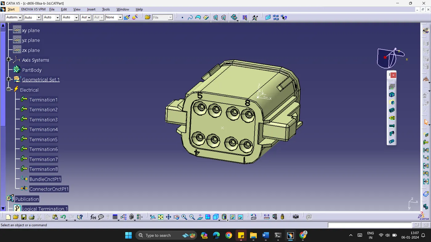
A. 3D models are given in .igs format to work on further. The 3D models are imported to Catia V5. As shown in the image below, the model has 8 terminals. A point is created in the middle of the terminals using Point command in the Part Workbench. The model is first defined as Connector, to give electrical properties. In the Geometrical set 1, it is evident that the model is given 8 terminal connector. The point between terminals is defined as Bundle Connection Point.
The other side of the model a point is created on the face. This point is known as Connector Connection Point. An axis system is created, taking the created point as its origin. This point is defined as Connector Connection Point.
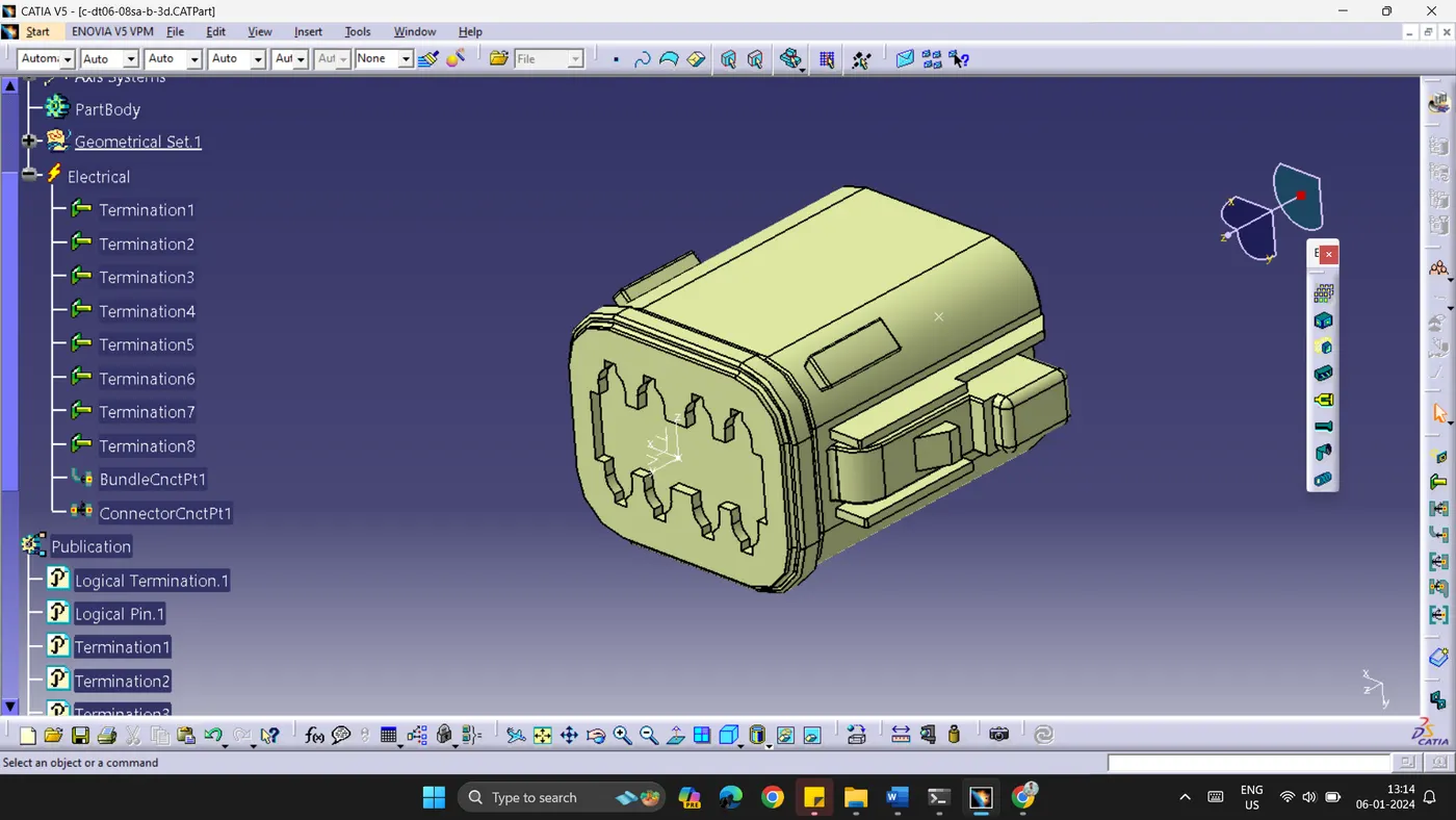
By doing the above shown procedure, one can define electrical properties to the 3D model. Which will be used further.
B. Another connector and a mounting clip are given. Both the models should be given electrical properties and later assemble them in Electrical Assembly Workbench.
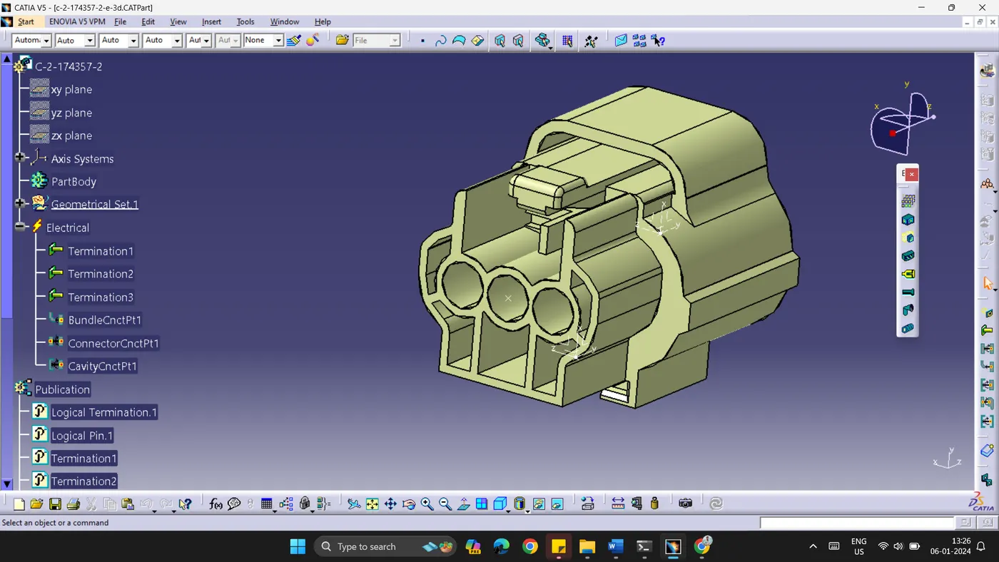
To begin, the model is defined as a Connector with 3 terminals. A point is created at the center of the face as shown below. This is defined as Connector Connection Point.
On the other side of the model, a point is created and defined as Bundle Connection Point. An axis is created at this point as origin.
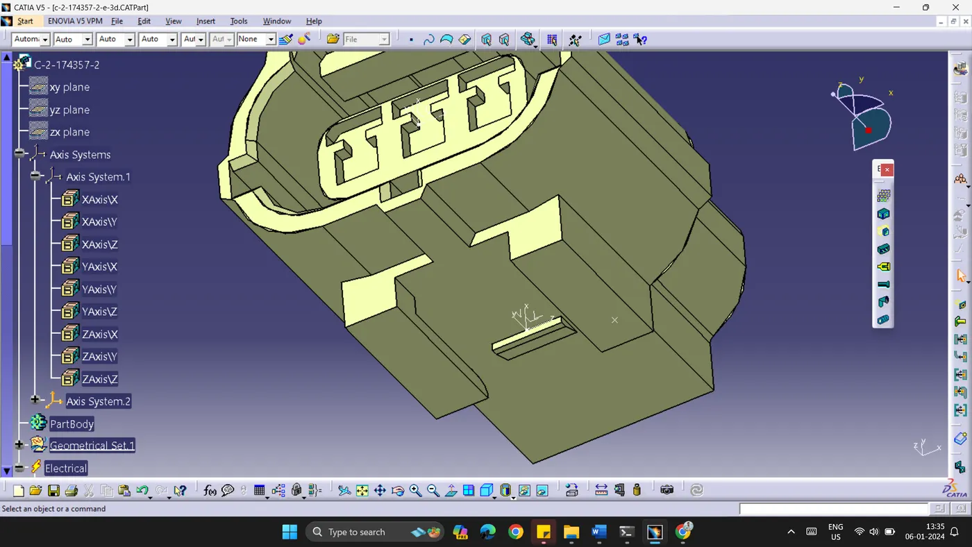
At the bottom of the connector, a mounting clip will be assembled. To make that assembly, the model is defined as cavity. To define Cavity Connection Point, a point is created as shown in the above image. An axis system is also created at that point.
The image given below is a 3D model of a mounting clip. A point is created on the mounting clip along with an axis system. The model is further defined as a cavity. As this is not an electrical component.
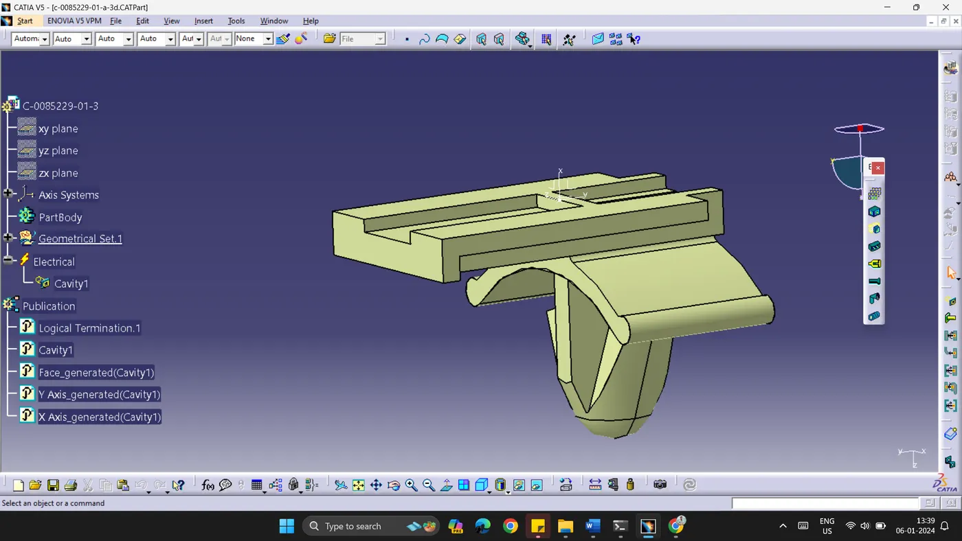
The two models are saved separately to work on further.
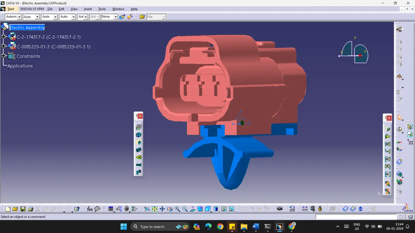
Two models are added to Electrical Assembly Workbench, using connect electrical devices command, two models are constrained as shown below.
Conclusion:
Given 3D models are defined with electrical properties, in Electrical Workbench in Catia V5.