Wiring harness design in CATIA V5 - 3D modeling Week 2 Challenge
AIM:
Download following connectors & Connector clip cad data from given link & define it as Electrical Connector using Electrical Part design Workbench. Define all the necessary properties to Connectors & Clip.
- Deutsch DT06 – 08SA ( https://www.te.com/usa-en/product-DT06-08SA.html)
- Tyco 174357-2 (https://www.te.com/usa-en/product-2-174357-2.html?source=header-match)
- Tyco 85229-1 – (https://www.te.com/usa-en/product-85229-1.html?q=85229&source=header) (these are the product )
INTRODUCTION TO WIRE HARNESS:
A wire harness is the exterior covering, or sheath, that protects an inner conductor or bundle of conductors. These inner components may already have sheaths for insulation and protection, or they may rely on the wire harness to create an ideal operational environment.
CONNECTOR DEFINATIONS IN CATIA V5:
Tyco 174357-2 :
1 )Create midpoint.
2) create Connector connection point.
3 )create Connector connection axis system .
4) create cavity connection point.
5) create cavity connection axis system .
6) Switch to Electric part design and define part as connector.
7) Define Connector connection point and cavity connection point.
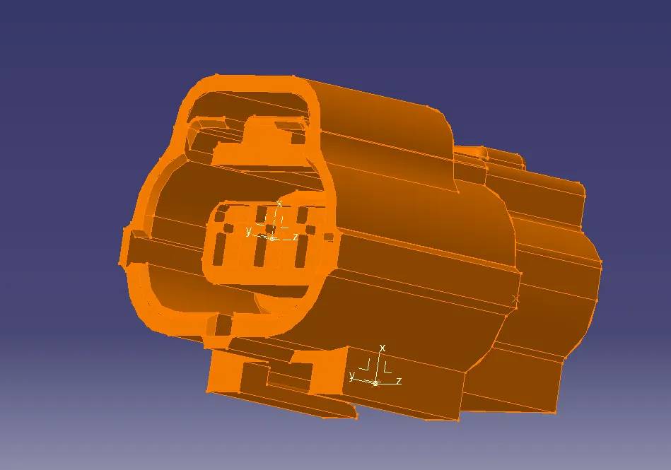
|( y-axis towards the face of connector, x_axis towards locking mechanism )
Tyco 85229-1 :
1) Create midpoint.
2) create cavity connection point.
3) create cavity connection axis system and orientation should be same as in connector .
4) Switch to Electric part design and define part as Mounting Equipment.
5) Define cavity connection point.
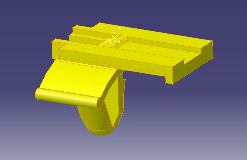
Deutsch DT06 – 08SA:
1 )Create midpoint.
2) create Connector connection point.
3 )create Connector connection axis system .
4) Switch to Electric part design and define part as connector.
5) Define Connector connection point and cavity connection point.
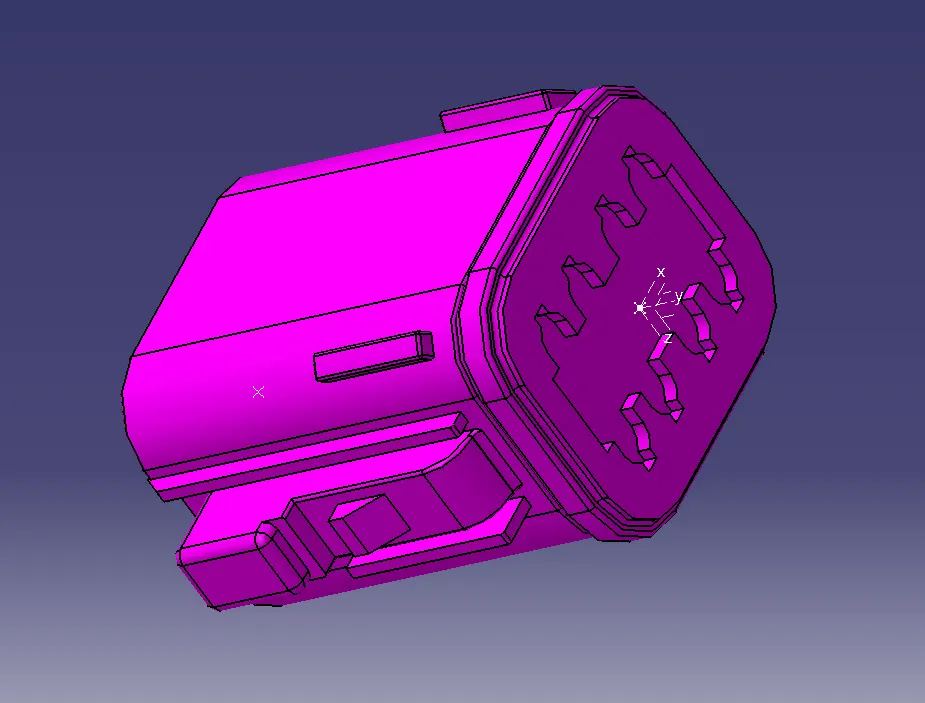
Electric 3D Assembly Design:
1) Import Connector and cavity / mounting clip.
2) Select Defing Eelectric connection
3) select cavity and then connector. the same repeat to connect required connector or cavity clips.
pin variation error:
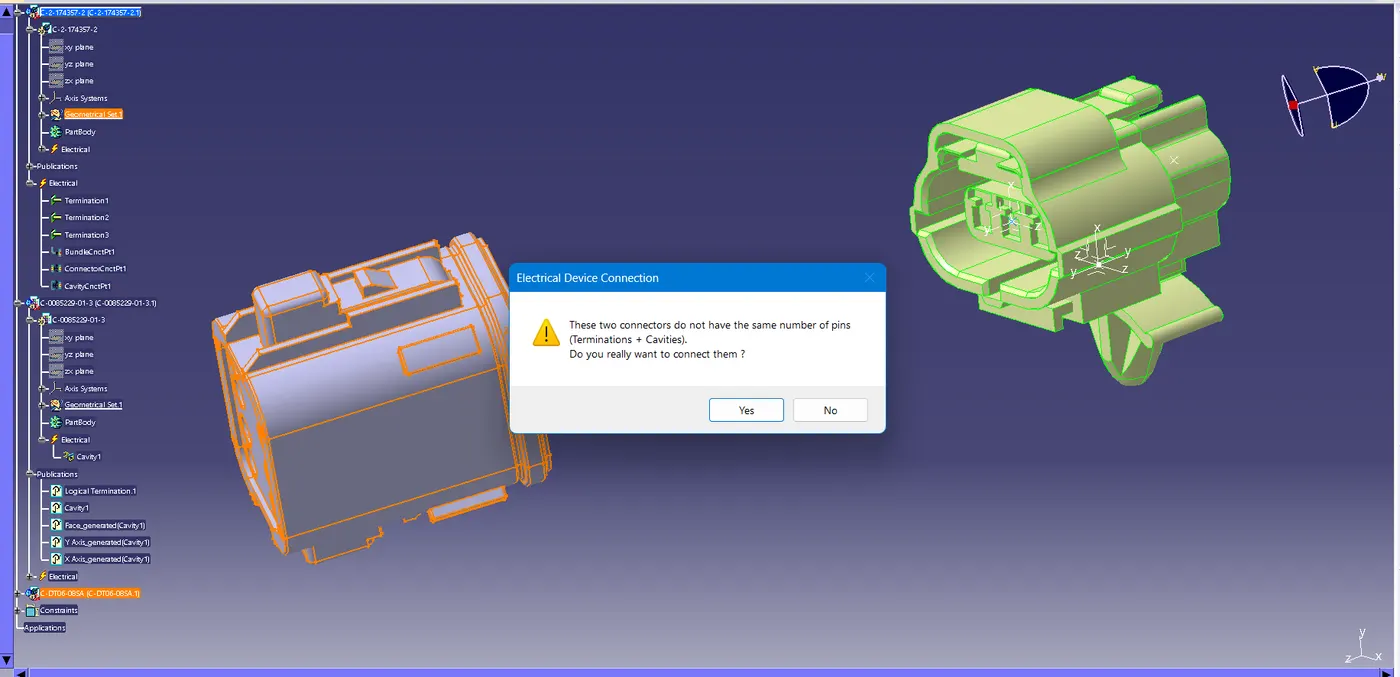
final assembly:
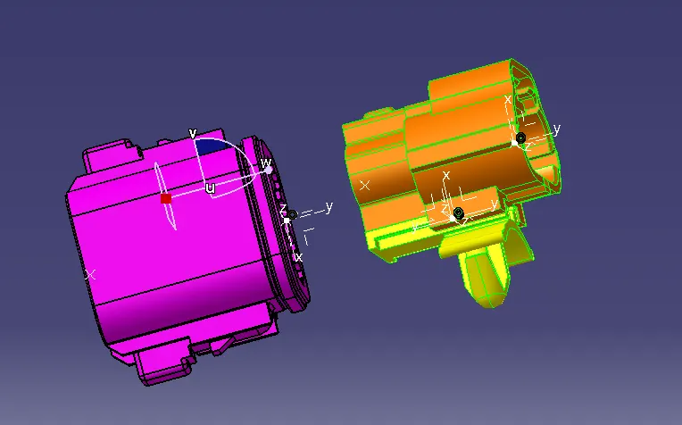
conclusion;
The connectors & Connector clip cad data from given link & define it as Electrical Connector using Electrical Part design Workbench sucessfully defind and assembled in electrical 3d assembly workbench.