Wiring harness design in CATIA V5 - 3D modeling Week 2 Challenge
Wiring Harness Design In CATIA-V5 - 3D Modeling:
AIM:
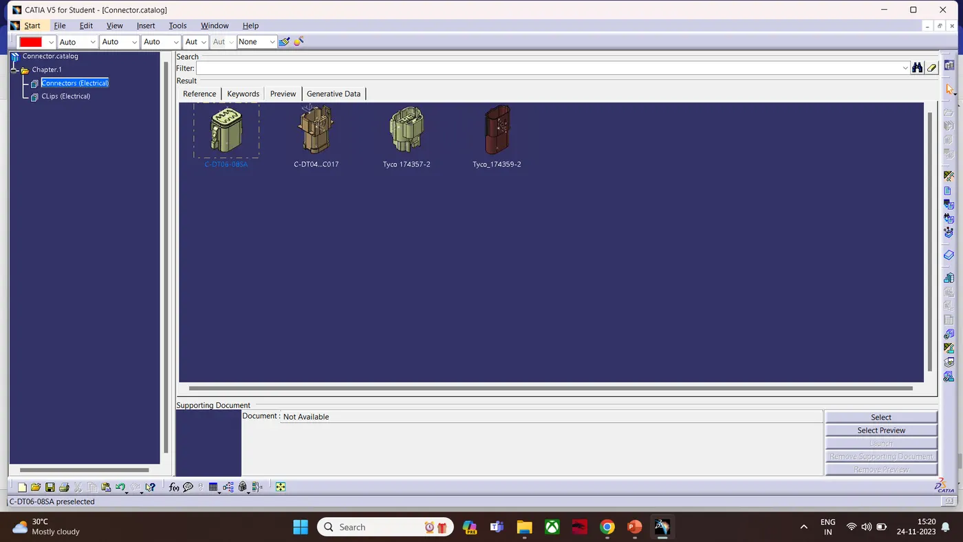
To Download The given connectors and Connector Clips. find the matting part to the given CAD data and define it as electric part design workbench.
Given Data:
1. DT06 – 08SA
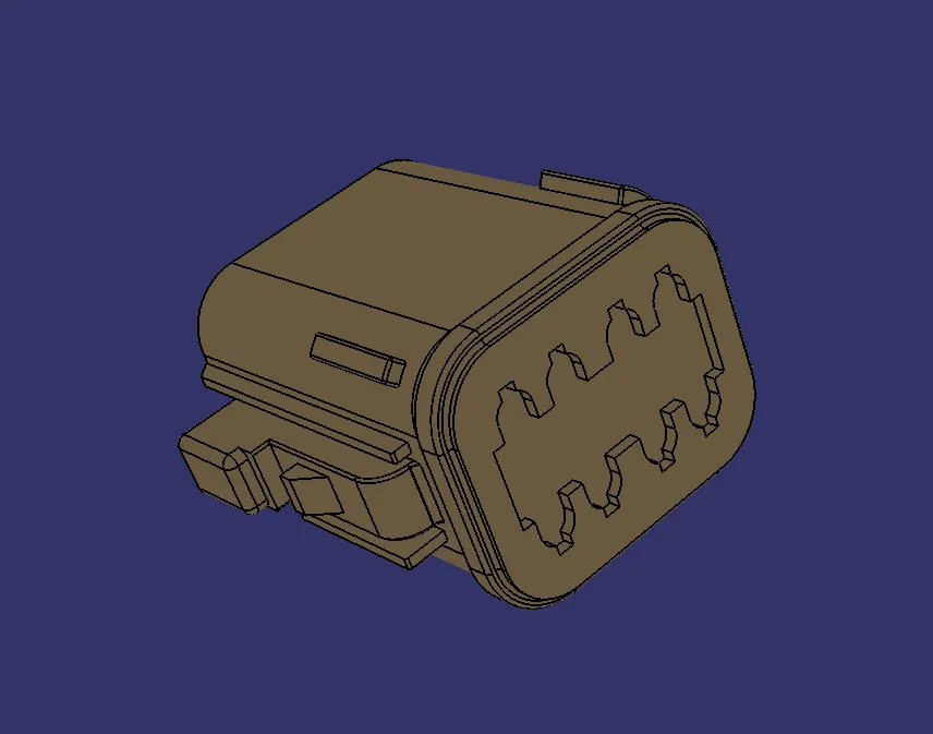
(We Need to find the matting part which is Female Connector and Connector Clips.)
2.Tyco 174357-2
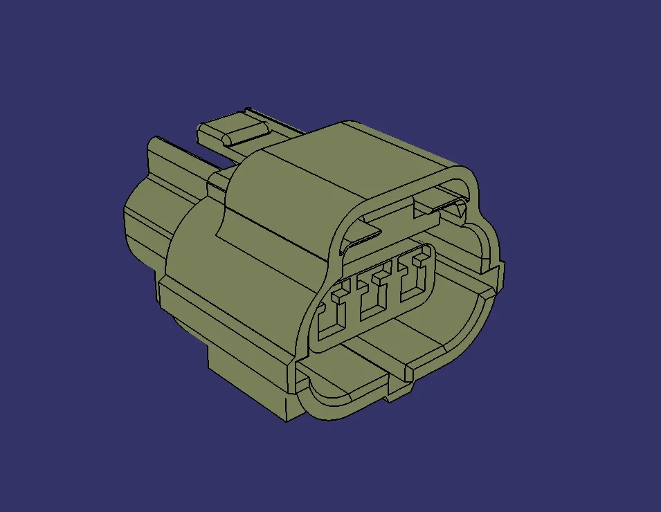
(We Need to find the matting part which is Female Connector)
3. Tyco 85229-1
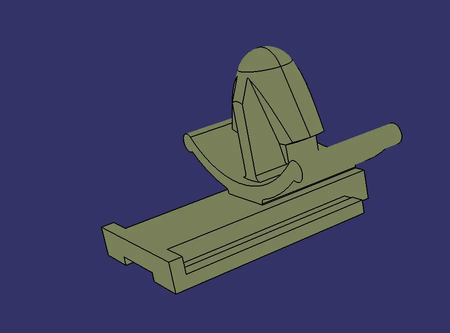
(This is the Connector clip of Tyco 174357-2)
Deutsch Connectors:
Electrical parts:
- DT06-08SA
- DT08-04PA
- C-1011-027-080
1.DT06-08SA
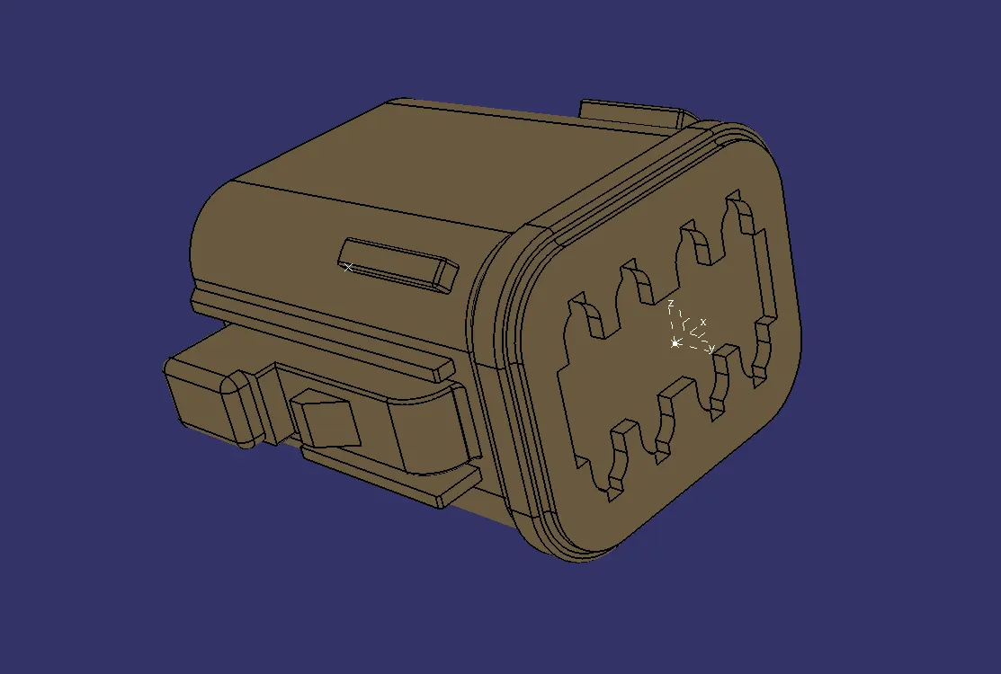
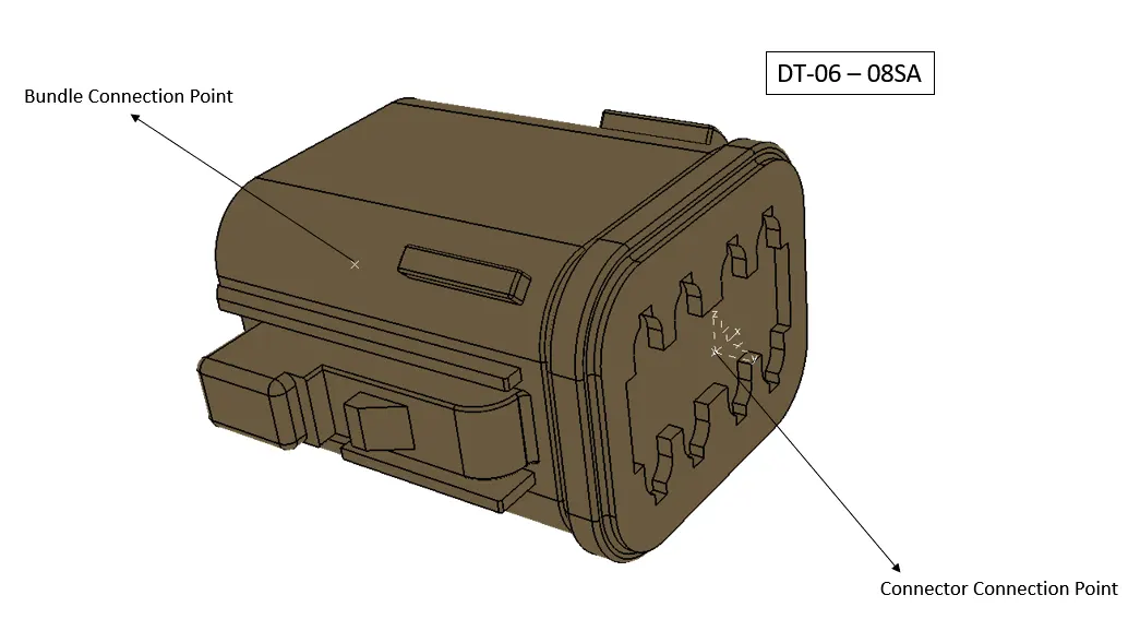
1.Define as Electric Connectors
2. Create a Midpoint in the bundle connection. then Define the point as Bundle COnnection Point
3. Create a Midpoint In the Connector Side. Then create an Axis at the Point
4. Then define the point as Connector Connection Point with respect to the axis.
2.DT08-04PA
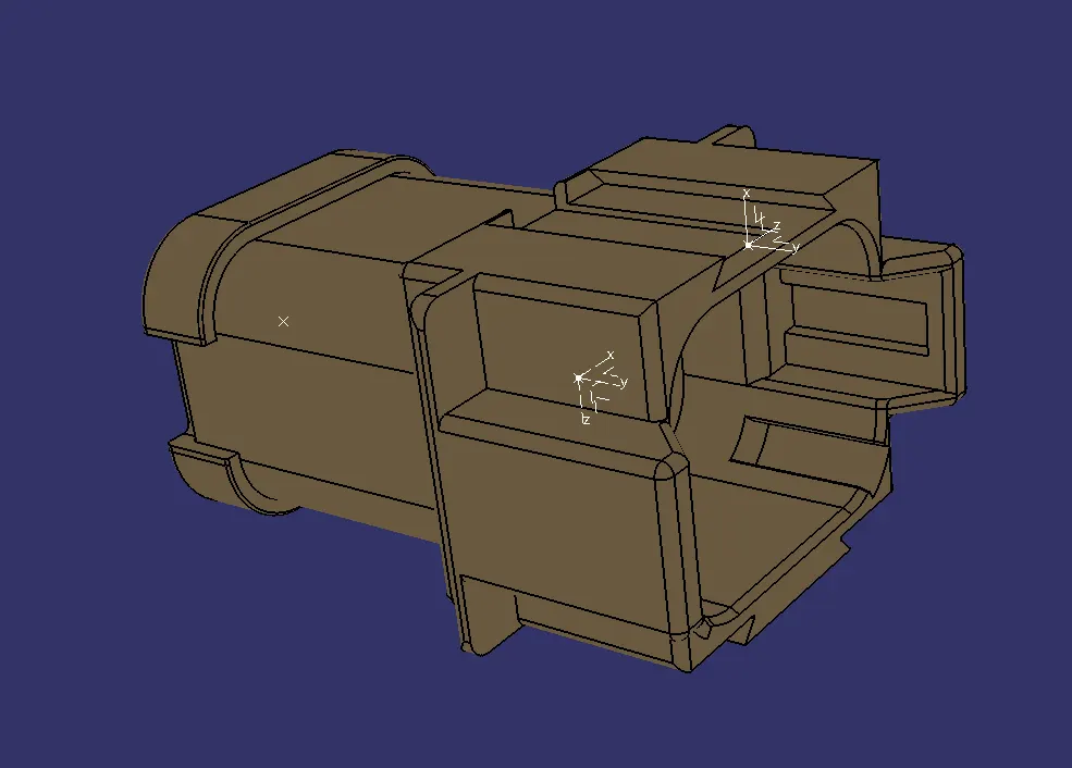
1.Define as Electric Connectors
2. Create a Midpoint in the bundle connection. then Define the point as Bundle COnnection Point
3. Create a Midpoint In the Connector Side. Then create an Axis at the Point
4. Then define the point as Connector Connection Point with respect to the axis.
5.Create a Point at the cavity connection point and define it as cavity connection point.
3.C-1011-027-080.
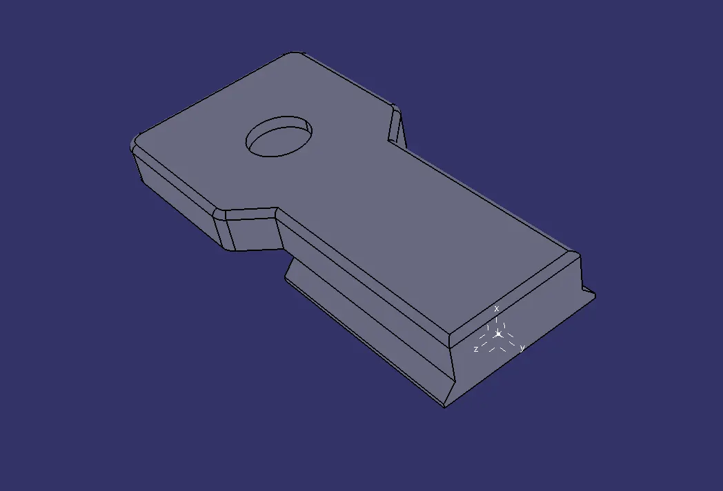
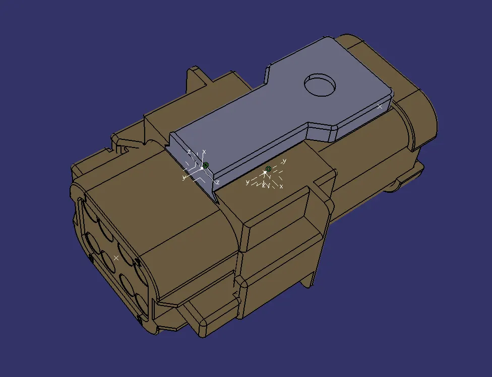
1.Create a point at The Cavity Connection Side. The Create a Axis System
2. Then Define It as Mounting Equipment
3. Then Define it As Cavity With respect to Axis System
DEUTSCH CONNECTORS: ( Geometrical Bundle)
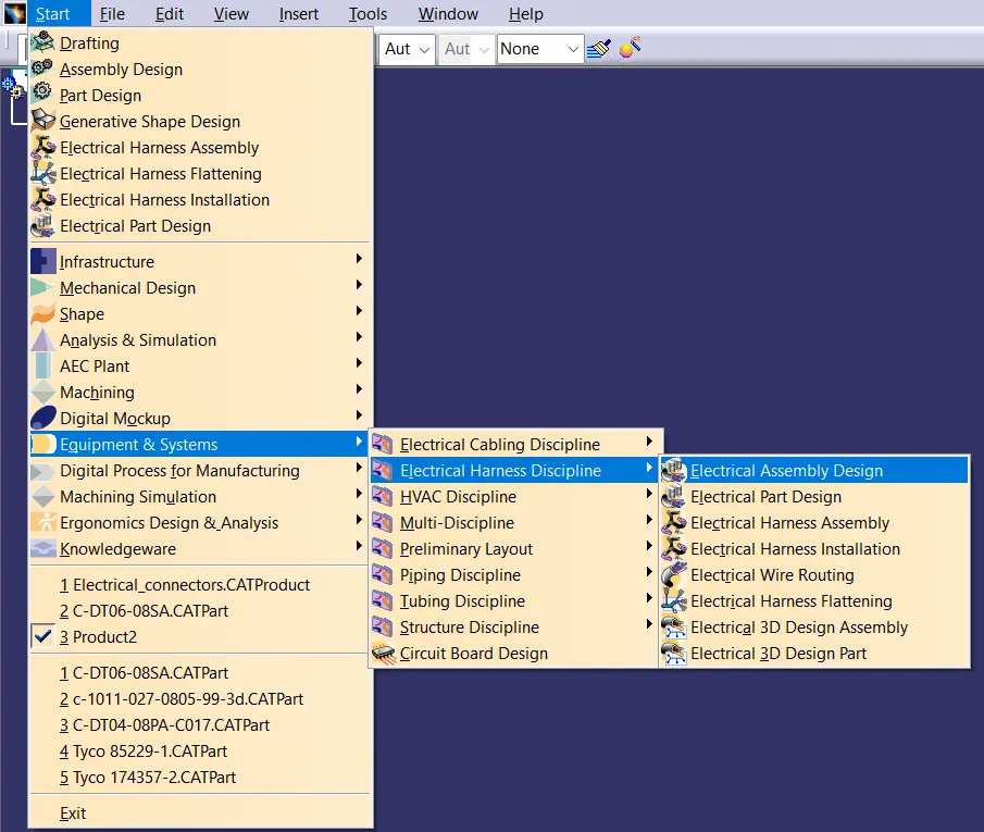
1. Change The Workbench to Electrical Assembly Design.
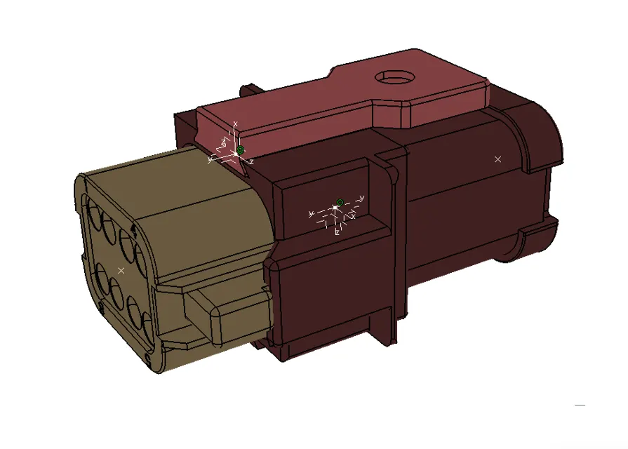
2.Insert all the Required Parts.
3.Join the DT06-08SA & DT04-08PA with the command of Connect Electrical Device.
4. Join The DT04-08PA &C-1011-027-080 With The command of Connect Electric Device.
TYCO CONNECTORS:
Parts:
1.Tyco 174357-2
2.Tyco_174359-2
3.Tyco 85229-1
1.Tyco 174357-2
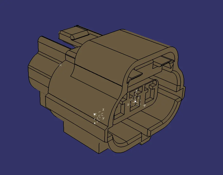
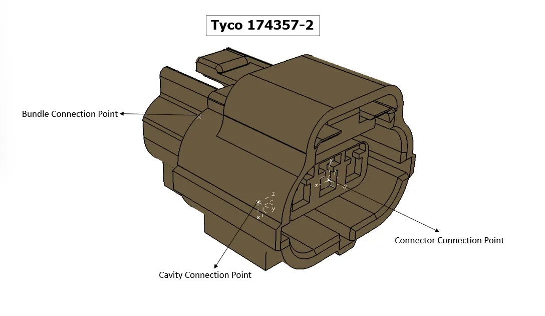
1.Define as Electric Connectors
2. Create a Midpoint in the bundle connection. then Define the point as Bundle COnnection Point
3. Create a Midpoint In the Connector Side. Then create an Axis at the Point
4. Then define the point as Connector Connection Point with respect to the axis.
5.Create a Point at the cavity connection point and define it as cavity connection point.
2.Tyco- 174359-2.
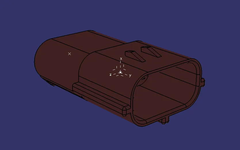
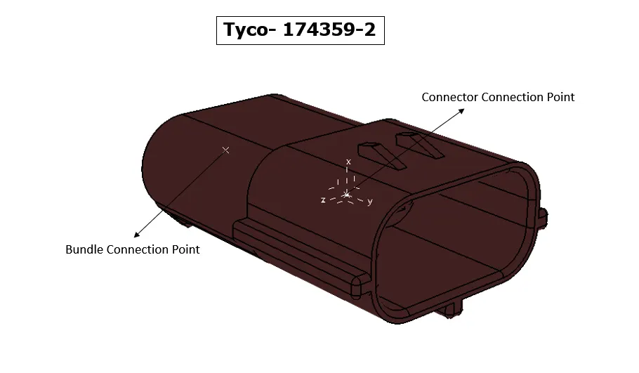
1.Define as Electric Connectors
2. Create a Midpoint in the bundle connection. then Define the point as Bundle COnnection Point
3. Create a Midpoint In the Connector Side. Then create an Axis at the Point
4. Then define the point as Connector Connection Point with respect to the axis.
3.Tyco 85229-1
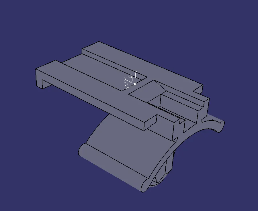
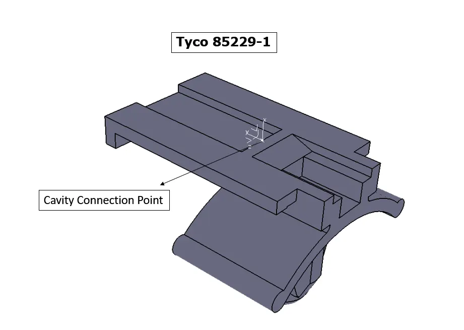
1.Create a point at The Cavity Connection Side. The Create a Axis System
2. Then Define It as Mounting Equipment
3. Then Define it As Cavity With respect to Axis System
DEUTSCH CONNECTORS: ( Geometrical Bundle)
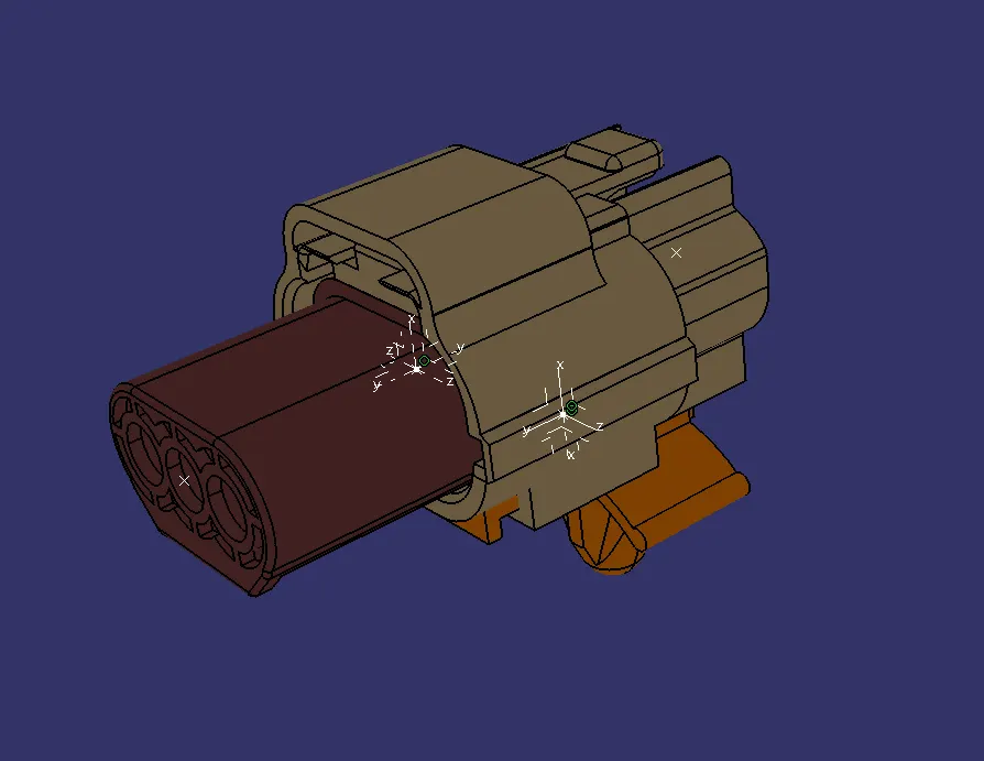
1. Change The Workbench to Electrical Assembly Design.
2.Insert all the Required Parts.
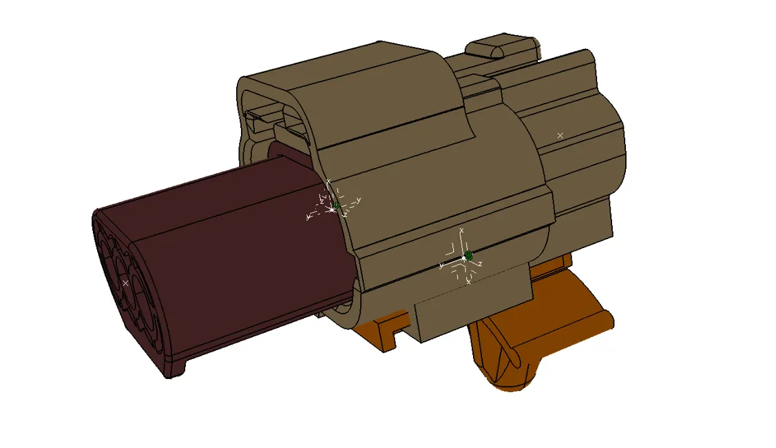
3.Join the Tyco 174357-2 & Tyco_174359-2 with the command of Connect Electrical Device.
4. Join The Tyco 174357-2 &Tyco 85229-1 With The command of Connect Electric Device.
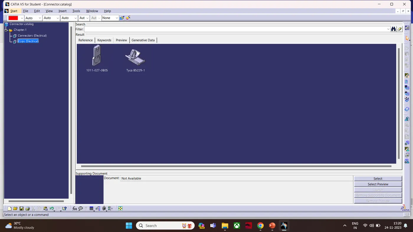
Catalogue: