Wiring harness design in CATIA V5 - 3D modeling Week 2 Challenge
Wiring Harness Design:
Week 2
Introduction
A wiring harness is an organized assembly of electrical wires, cables, and connectors used in various industries to transmit power and signals efficiently within devices, machines, or vehicles. It simplifies installation, maintenance, and repairs by bundling all necessary wires into a single unit, eliminating the need for individual routing and connections. The harness provides mechanical protection and organization, with wires often color-coded or labelled for easy identification. It is widely used in automotive, aerospace, electronics, and industrial applications. The primary purpose is to ensure reliable electrical connections and optimize the performance of complex systems, enhancing safety and efficiency in a wide range of applications.
About components:
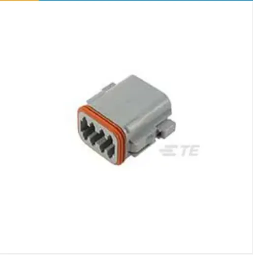
(a)DT06-08SA
The DT06-08SA connector is a rectangular-shaped connector designed as a housing for female terminals, making it suitable for wire-to-wire connections. It offers the advantage of being sealable, providing protection against environmental elements. While not a hybrid connector, it incorporates an integrated locking feature within the housing for secure connections. The connector is designed to terminate both wires and cables, offering versatility in its applications. With its robust construction and reliable performance, the DT06-08SA connector is a dependable choice for various industries and electrical systems.
Configuration Features
- Number of Positions: 8
- Number of Rows: 2
- Blank Cavity Position: 0
Electrical Characteristics
- Operating Voltage (VAC): 250
- Operating Voltage (VDC): 250
- Nominal Voltage Architecture (V): 12, 24, 48
Contact Features
- Contact Type: Socket
- Mating Pin Diameter: 1.59 mm [ .063 in]
- Contact Current Rating (Max) (A): 13
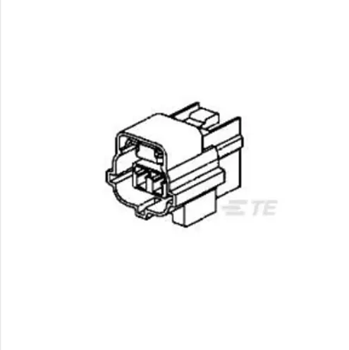
(b)2-174357-2
The 2-174357-2 connector is a rectangular-shaped connector designed as a housing for female terminals, making it suitable for wire-to-wire connections. Similar to the DT06-08SA connector, it offers the advantage of being sealable, providing protection against environmental factors. While not a hybrid connector, it incorporates an integrated locking feature within the housing for secure connections. With its reliable construction and primary locking mechanism, the 2-174357-2 connector ensures a dependable and robust electrical connection for various applications.
Configuration Features
- Number of Positions: 3
- Number of Rows: 1
Electrical Characteristics
- Operating Voltage (VDC): 12
- Nominal Voltage Architecture (V): 12
Contact Features
- Contact Type: Receptacle
- Contact Size: 1.8mm
- Mating Tab Width: 1.8 mm [ .071 in]
(c)85229-1
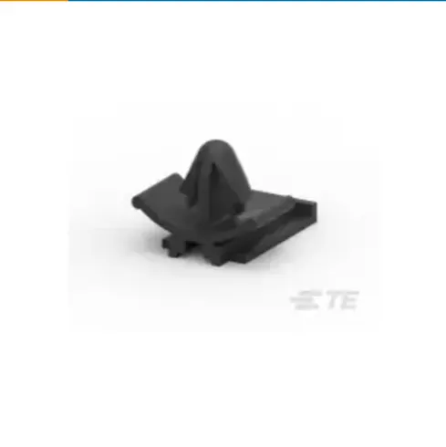
The 85229-1 mounting clip is an automotive connector accessory used specifically for mounting connectors. It serves as a clip to securely fasten a connector in place. The mounting clip is designed to withstand a wide operating temperature range, from -40°C to 120°C (-40°F to 248°F), making it suitable for automotive applications exposed to varying environmental conditions. Additionally, it meets the UL 94V-2 flammability rating, ensuring compliance with industry standards for fire resistance. The 85229-1 mounting clip provides a reliable and safe solution for securing connectors in automotive systems.
Body Features
- Primary Product Material: PA
Working with the given components:
These components are available at te.com and their CAD data can be downloaded as .stp or. igs or .dxf files. Convert these to files compatible format then open them in part file.
(a)DT06-08SA
Identify the mating surface and the bundle surface. Create points on the centre of the mating surface of the connecting and the bundle points. For that create point using between subtype. Insert an axis system making the connector connecting point the origin. Arrange the principal axes such that y-axis is normal to the mating surface and x-axis directed towards the locking mechanism.
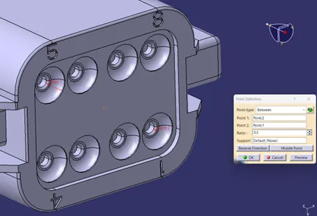
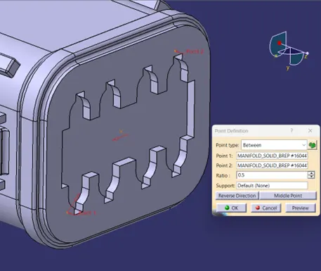
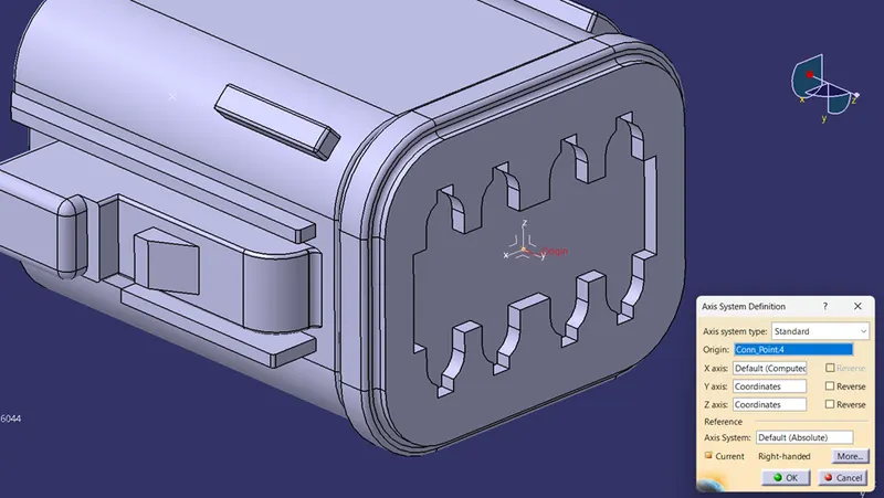
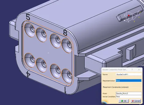
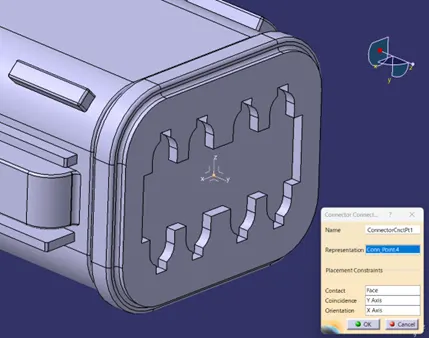
Switch to Electrical Part Design workbench. Click on Define Connector and select the given component. Now define the bundle connection point. Use the normal surface as the represent and select the point. Make the same surface as the initial condition. Now click on the Define connector connection point. Select the connector connection point as the origin of the axis system. Make the reference surface as the surface on which the origin lies. Y-axis being the connecting direction and x-axis as orientation direction. Save the file in the desired location.
(b)2-174357-2
Identify the mating surface and the bundle surface. Create points on the centre of the mating surface of the connecting and the bundle points. For that create point using between subtype. Insert an axis system making the connector connecting point the origin. Arrange the principal axes such that y-axis is normal to the mating surface and x-axis directed towards the locking mechanism.
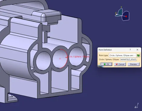
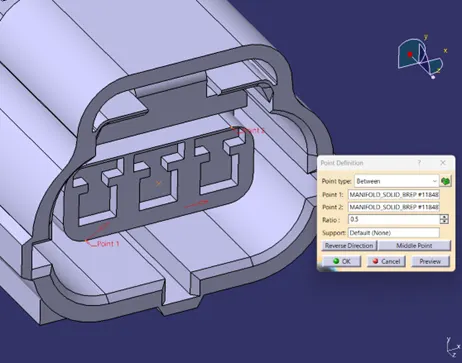
Switch to Electrical Part Design workbench. Click on Define Connector and select the given component. Now define the bundle connection point. Use the normal surface as the represent and select the point. Make the same surface as the initial condition. Now click on the Define connector connection point. Select the connector connection point as the origin of the axis system. Make the reference surface as the surface on which the origin lies. Y-axis being the connecting direction and x-axis as orientation direction. Save the file in the desired location.
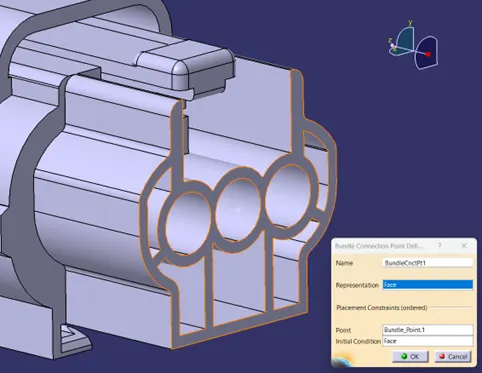
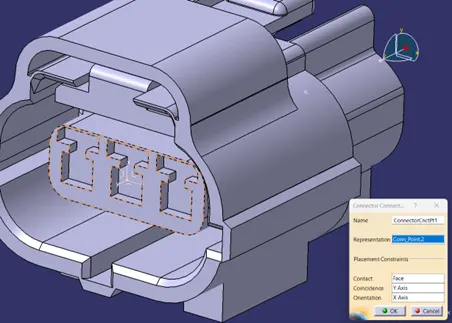
(c)85229-1
The process is slightly different from the connectors as it is a mounting clip. Identify the edge and the surface which comes in contact of the mounting area. In part design workbench, create a point in the middle of the edge. Place an axis system on the point. Arrange the principal axes such that y-axis is normal to the mating surface and x-axis directed towards the locking mechanism.
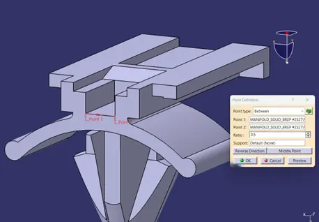
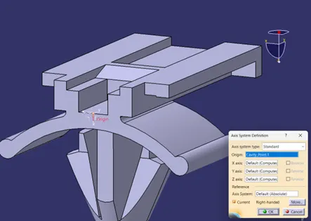
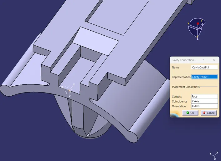
In the Electrical Part Design click on Define Mounting Component and select the component. Now click on Define Cavity and select the origin as the represent point. Make coincidence with y-axis and orient it with x-axis.
Conclusion:
The process of defining properties for components in part design and electrical part design workbenches involves a systematic approach. For connectors, the steps include identifying mating and bundle surfaces, creating centre points, and establishing an axis system with the connector connecting point as the origin. The y-axis aligns with the mating surface's normal direction, and the x-axis points towards the locking mechanism. In the Electrical Part Design workbench, defining connector and bundle connection points and setting the orientation is crucial.
For mounting clips, the process involves identifying the edge and surface in contact with the mounting area, creating a midpoint point, and placing an axis system. The y-axis aligns with the mating surface's normal direction, and the x-axis points towards the locking mechanism. In the Electrical Part Design workbench, defining the mounting component involves selecting it, setting the origin as the represent point, and aligning the y-axis and orienting it with the x-axis. These defined properties ensure accurate integration and optimal performance of components in various industries, enhancing productivity and innovation.
Files Attached:
Connector_part_files.zip
Wiring Harness Design.docx