Wiring harness design in CATIA V5 - 3D modeling Week 2 Challenge
STEP 1: All the connectors were downloaded and saved on to proper place for easy access.
STEP 2: four geometric parameter were created those were:
a. connector connection point
b. connector connection axis
c. bundle connection point
d. bundle connection axis
as shown in below picture :
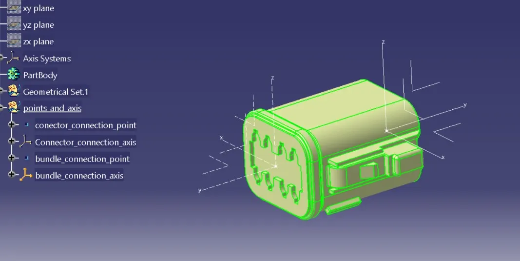
While defining the axis it was assured that the axis direction are taken such a way that its consistent with the mating connector and have some logic to remeber,
connector entry direction was taken as y-axis
locking direction was given as x-axis
z- comes as a result of above two defination.
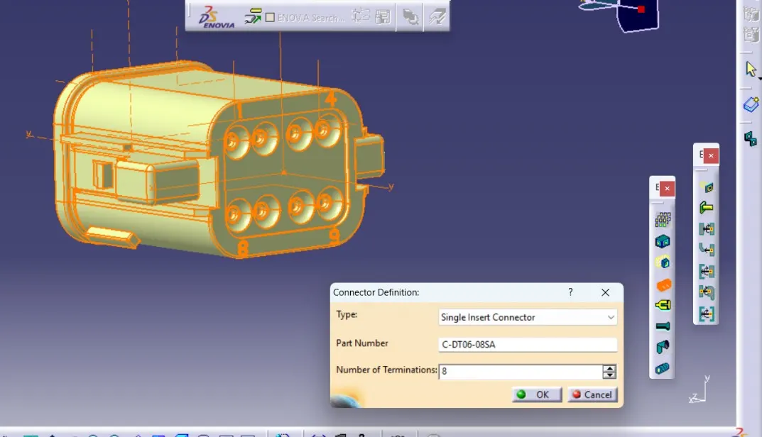
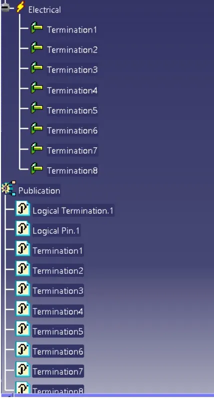
STEP 3: Conector is defined as 8-pole connector as shown below:
STEP 4: Connector connection point was defined as shown below: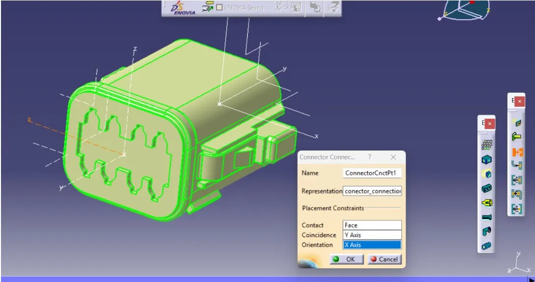
STEP 5 : Bundle connection point was defined as below: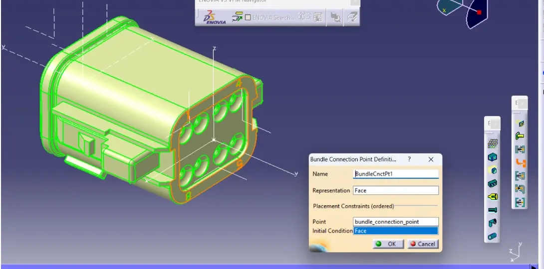
Step 6: after this the part was saved
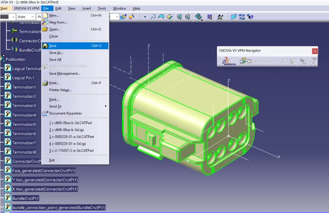
step 7: creating catlogue by stating new catlogue document and multiple families were added for further use as shown below: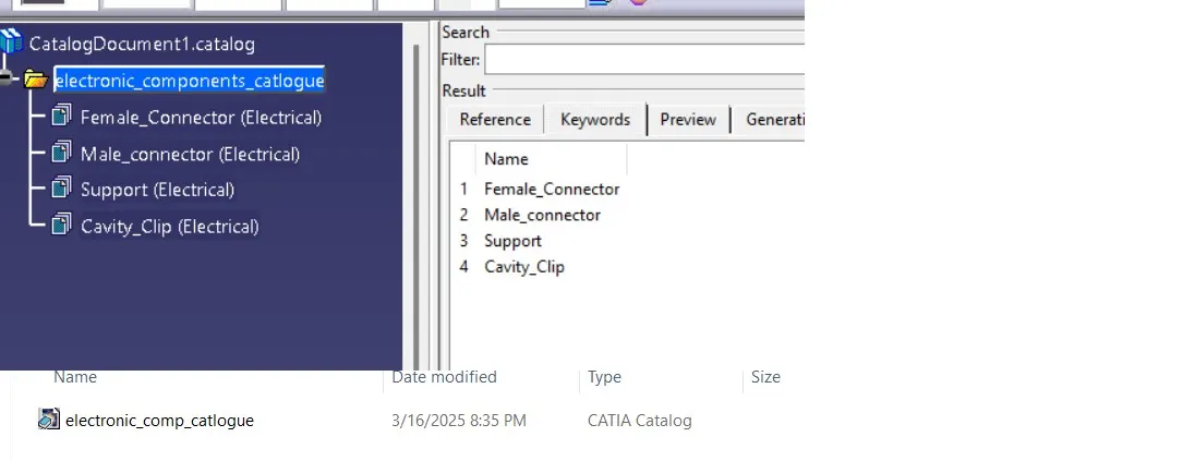
saved saved as catalogue doc.
step 8: added connector to catlogue as shown bleow: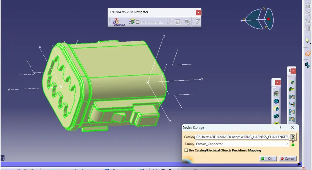
--------------------------------------------------------------------------------
for c2-174357-2 same procedure has been followed except we have cavity connection provision also , so we had defined cavity connection point as well as shown below: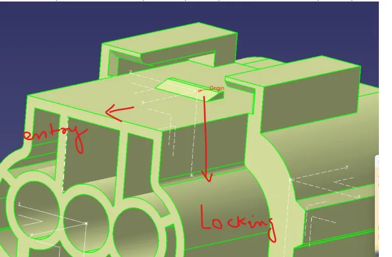
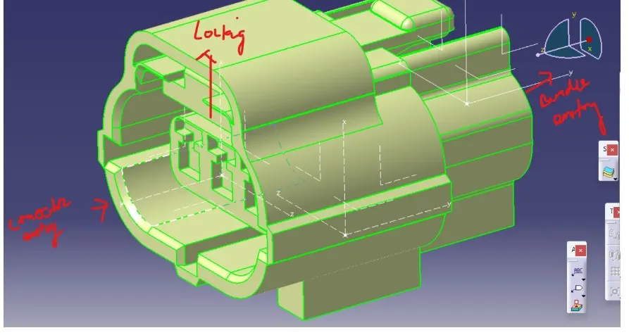
defined as three pole connector
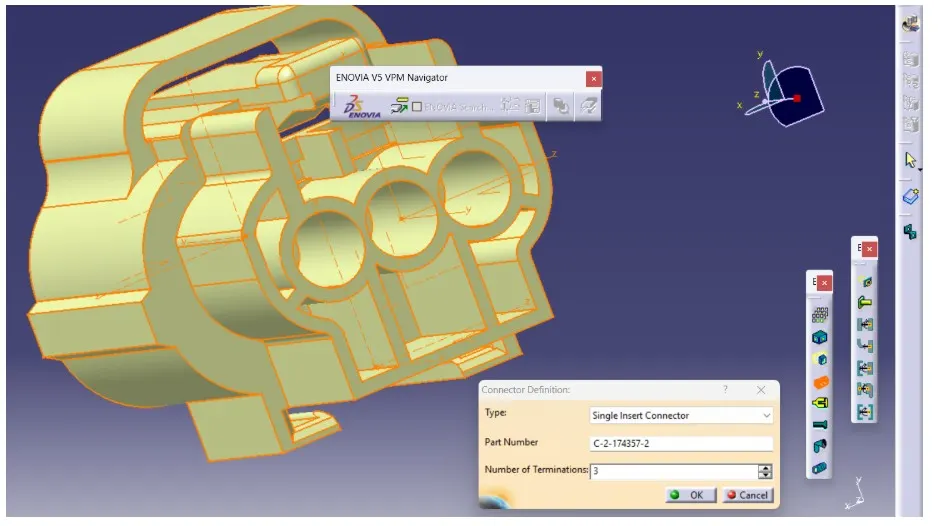
connector connection point defined
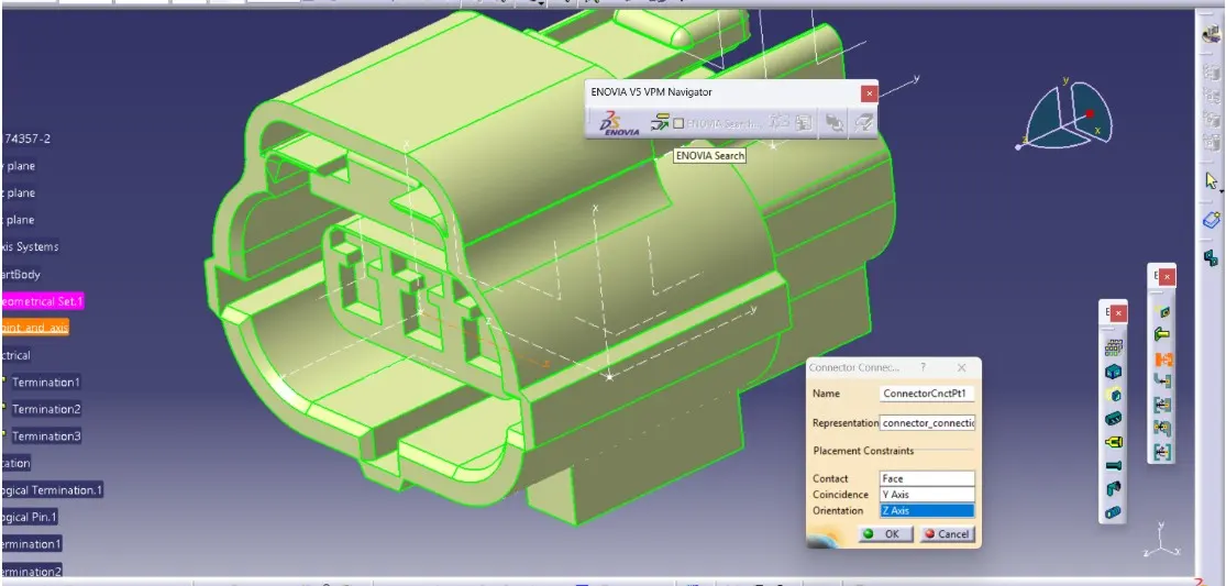
defined bundle connection point: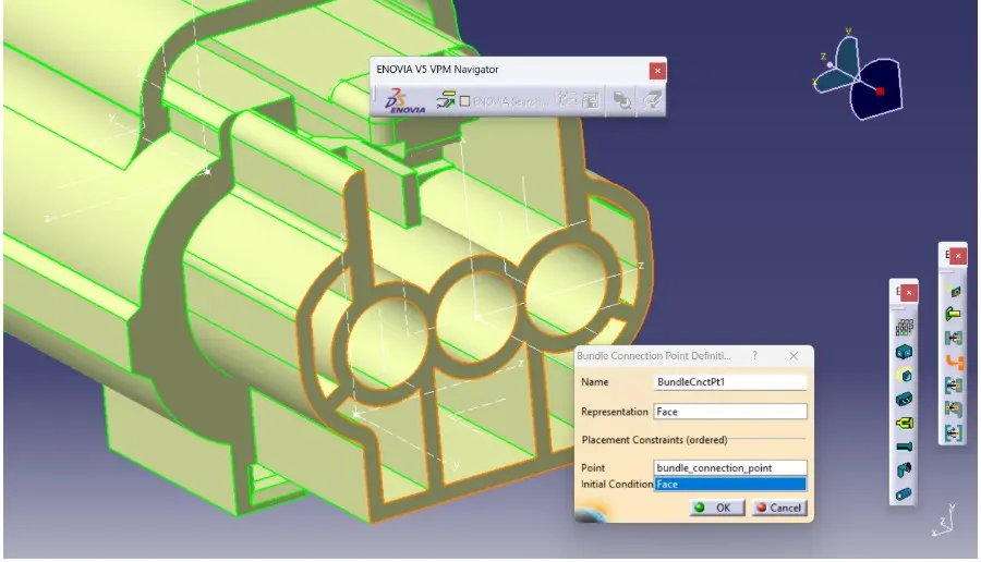
define cavity connection point: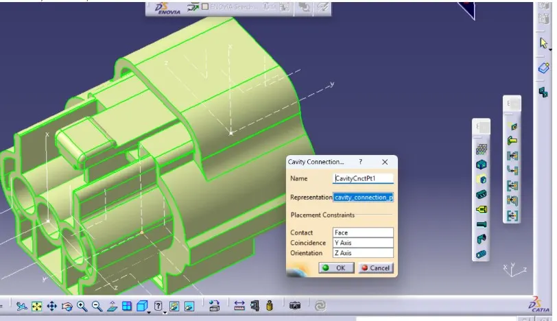
save on catlogue :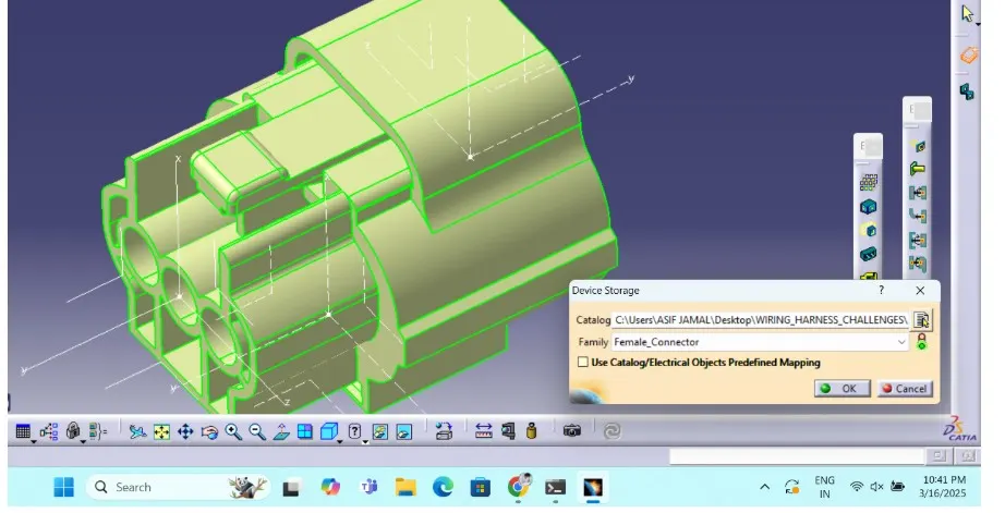
define it as mounting equipment.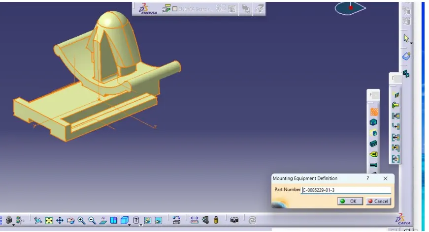
same for the cavity clip define cavity connection point as shown below: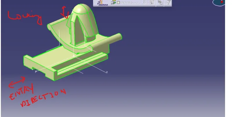
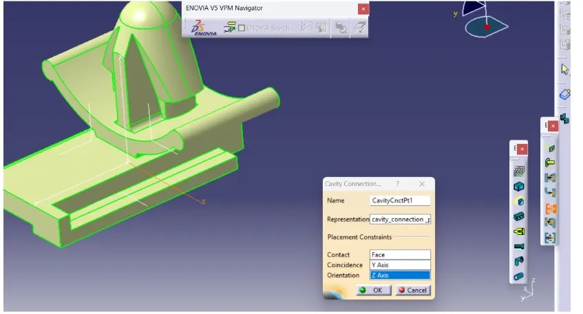
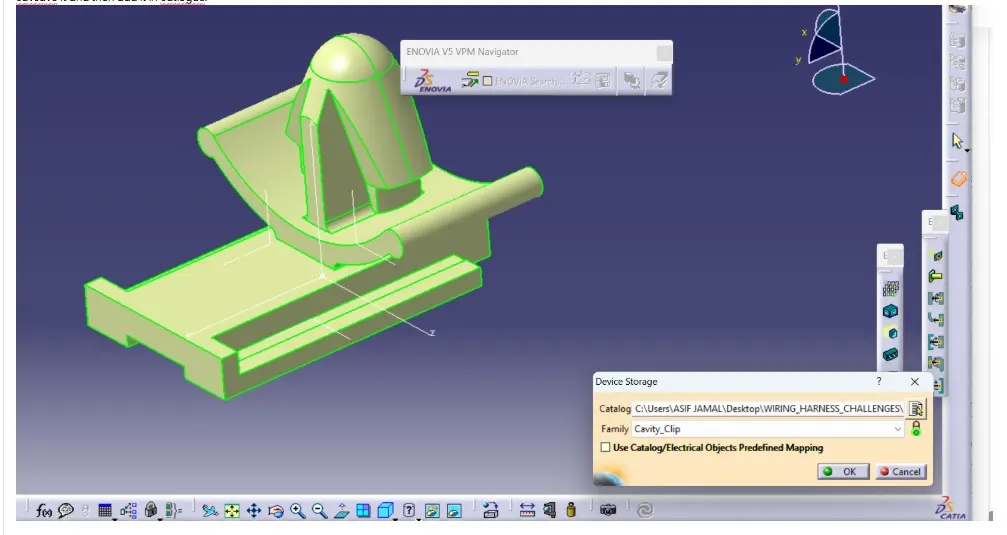
save it and then add it in catalogue: