Wiring harness design in CATIA V5 - 3D modeling Week 2 Challenge
REPORT:
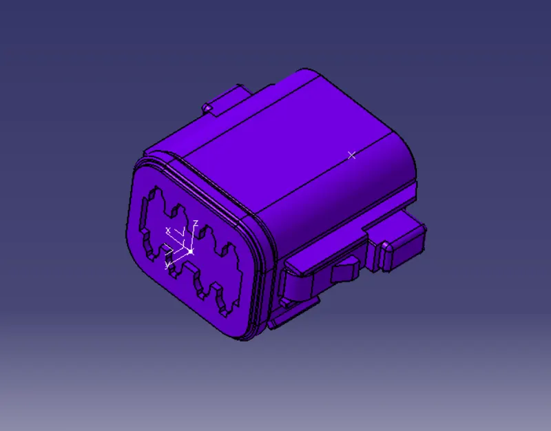
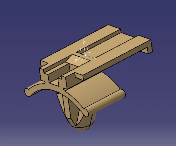
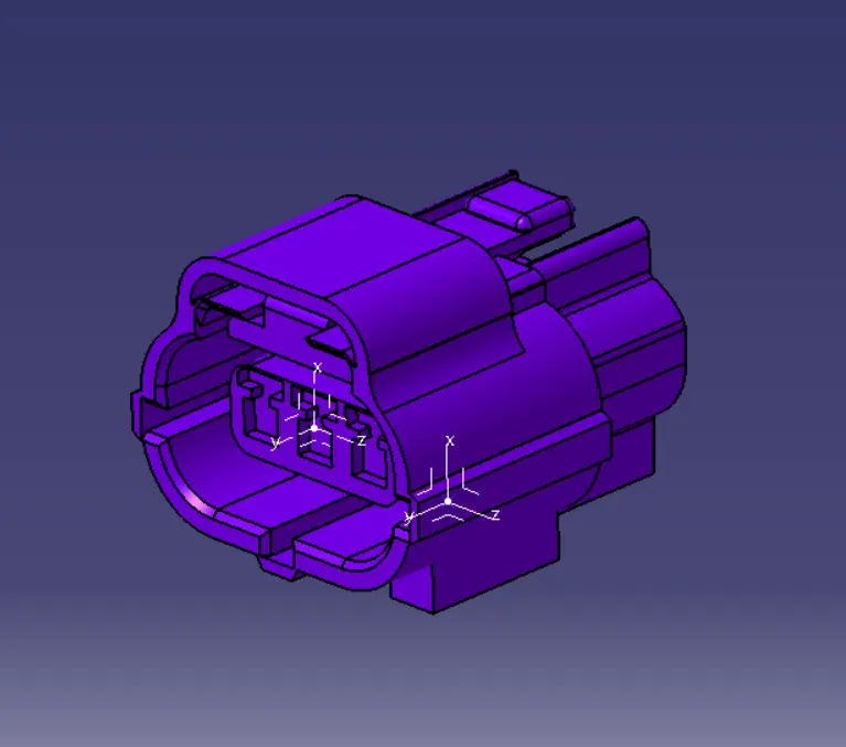
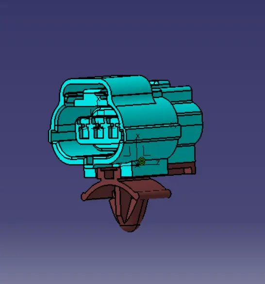
For defining the electrical connector first step is to create or download the component. and after that i checked the components for the compatibility. after that i defined the parameters which is needed for the ekectrical assembly. first created a point in the rear end where wire has to be connected and another point is created at the other end which is mating area. and an axis is created where y is in the coinside direction and x is in the locking direction of the connector and z to the left and right direction. it was done in the part workbench. after that go to the electrical part workbench , and first define the connector as an electrical part. and define the connector connection point. where we created the points and axis. aftere that the clip is defined. for that open the clip part which is downloaded from the website,and created a point where the connector and clip are assembled. and an axis is created at the point as we created earlier,used the same procedure. after that go to the electrical part workbench and defined the clip as an electical mounting equipment. after that i defined the cavity connection point. with the point and axis created . after defining the parts as an electrical component i go to the electrical assembly workbench. and assembled part using the command connect electrical part.