Wiring harness design in CATIA V5 - 3D modeling Week 2 Challenge
Wiring Harness,
A connector refers to a device or component that allows for the secure and reliable connection of electrical wires and signals between various components or systems in a vehicle. It serves as a junction point where different wires can be joined together or connected to different electrical components.
Connectors in automobile wiring harnesses are crucial for maintaining the integrity and functionality of the electrical system in a vehicle. They allow for easy assembly and disassembly of components, facilitate troubleshooting and repair processes, and ensure reliable electrical connections that are resistant to vibration, moisture, and other environmental factors that vehicles may encounter.
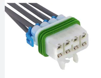
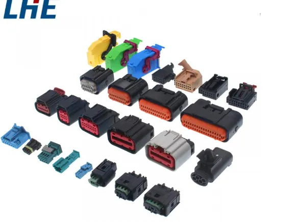
Connector clip,
A connector clip is a specific type of device used to secure and lock the connectors together. It is often a small plastic or metal component that attaches to the connectors, ensuring a firm and reliable connection.
The use of connector clips in automobile wiring harnesses helps ensure the integrity and continuity of electrical connections, reducing the risk of electrical failures, intermittent connections, or signal disruptions. It is an important component in maintaining the reliability and performance of the vehicle's electrical system.
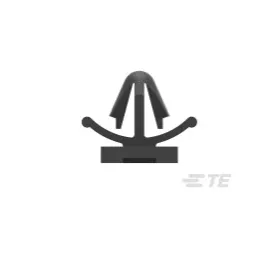
Creation of std. catalogue,
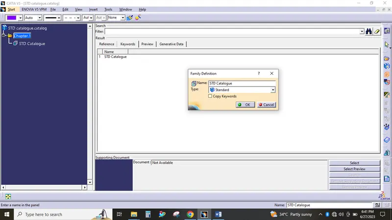
Go to file->new->catalogue document-> add family-> Name as Std.catalogue->Type as standard and save it in the desired location.
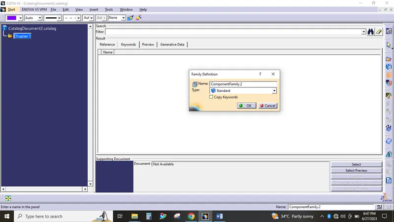
Catalogue editor,
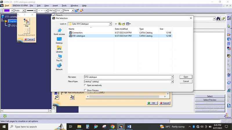
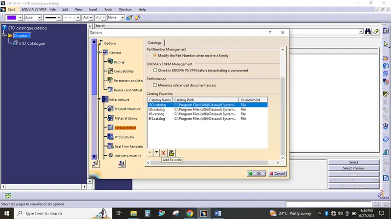
here i have added the created catalogue in the catia v5 software, for often uses
Electrical catalogue creation,
The above mentioned were used as it is to made the electical catalogue. The only changes are the names and catalogue type as electrical.
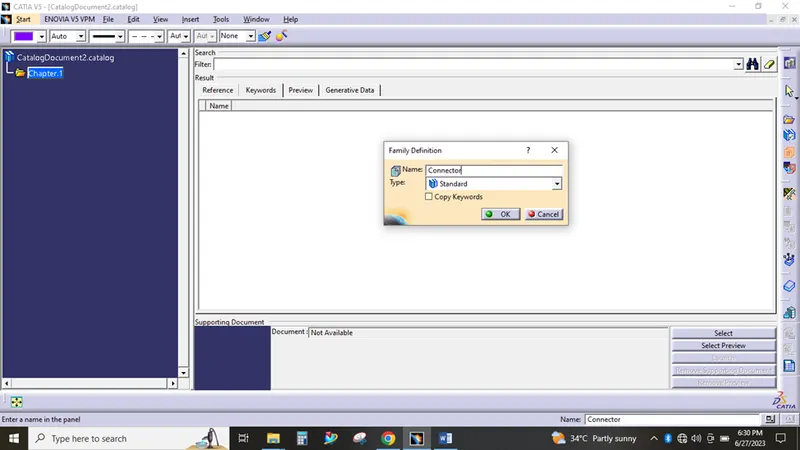
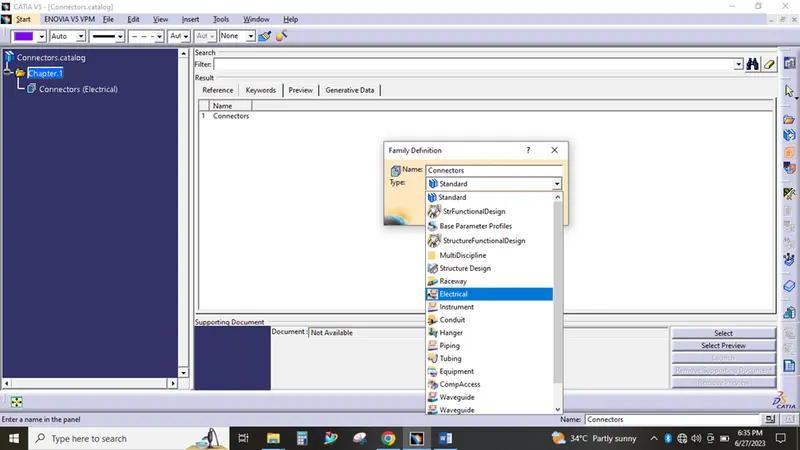
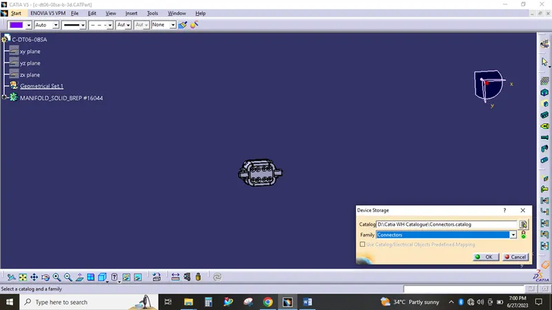
The below window is used to add the electical catalogue into catia v5
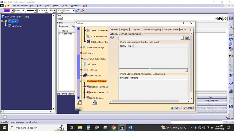
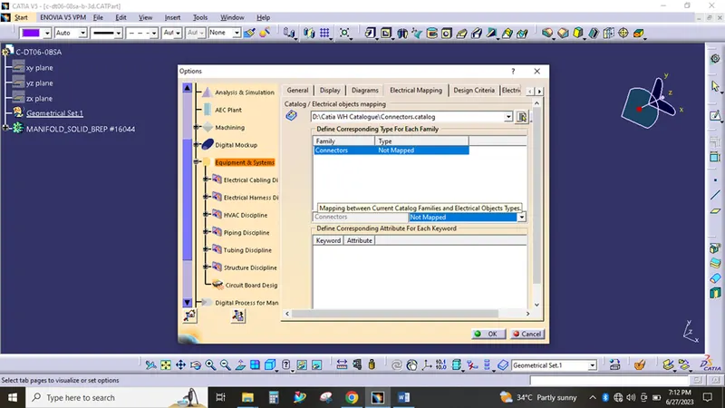
The given connector and clip links has used, the 3d parts has downloaded and saved in the desired location.
Steps involved in defining a part as an electrical part,
1. Creating necessary geometry parameters,
2. Defining part as an connector / Mounting Equipment,
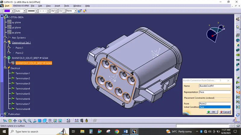
3. Defining bundle entry point,
4. Defining connector connection point,
5. Defining cavity connection point,
6. Storing the device in the catalogue.
Creating necessary geometry parameters,
To define a 3D cad part as electrical part the appropriate points and axis systems has placed in the connector cennection point and bundle entry point.
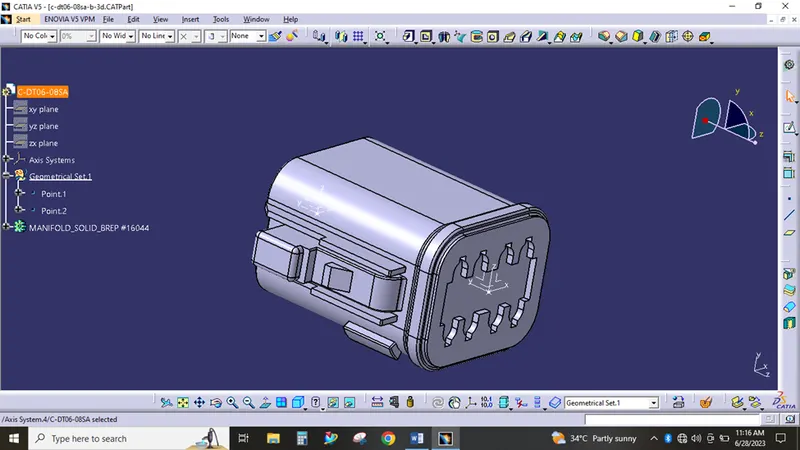
Defining part as an connector,Defining bundle entry point,
After defining, the part has stored in the catalogue,
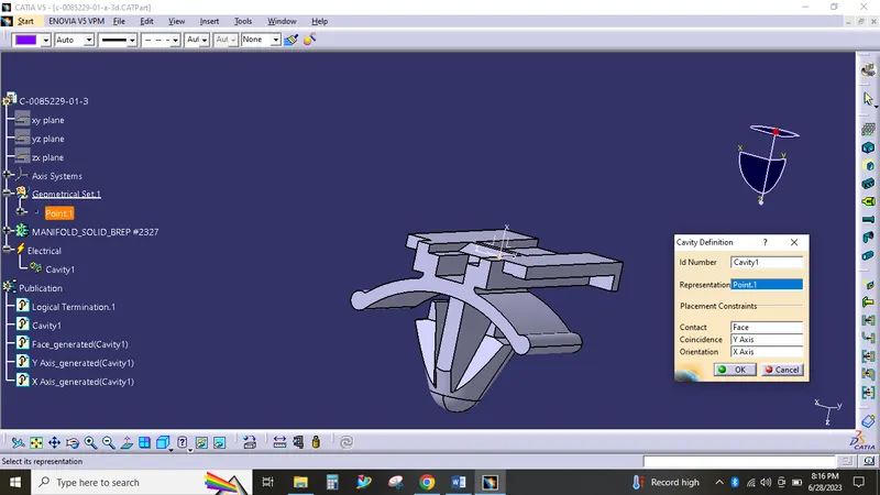
Defining cavity connection point,
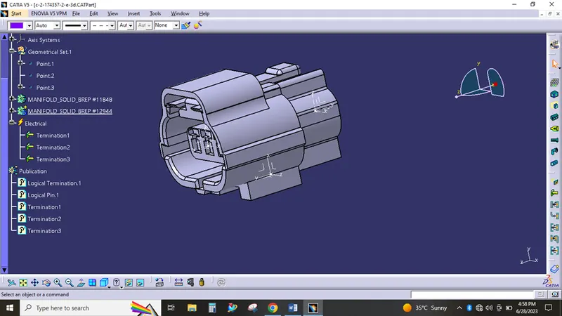
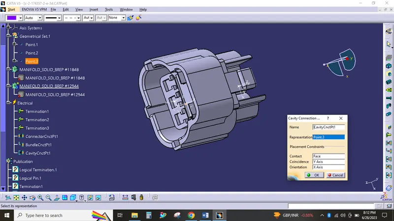
Defining cativy,
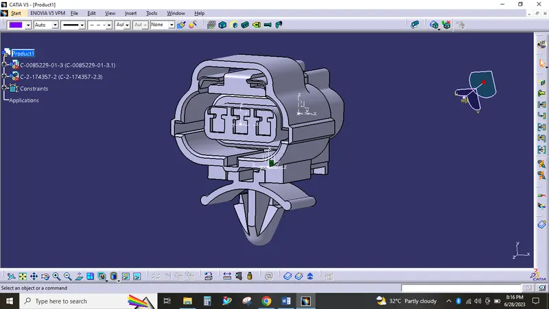
Connector assembled with the mounting clip.