Wiring harness design in CATIA V5 - 3D modeling Week 2 Challenge
AIM
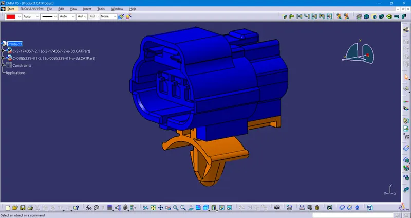
To Download Connectors & Connector clip cad data from given link & defining them Electrically using Electrical Part design Workbench, defining all the necessary properties to Connectors & Clip and creating the electrical assembly and further creating Catalogue for the components.
INTRODUCTION
Wiring Harness
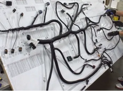
A wire harness is a specially designed system that keeps numerous wires or cables organized. It is a systematic and integrated arrangement of cables within an insulating material. The purpose of the wiring assembly is to transmit a signal or electrical power.
Basics of Electrical Distribution System (EDS) & Wiring Harness
Electrical Distribution System (EDS)
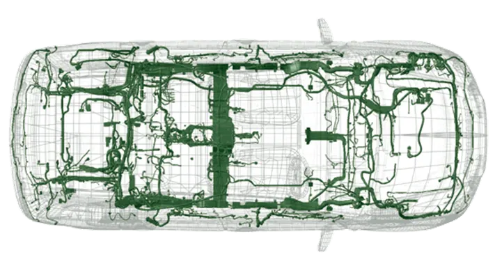
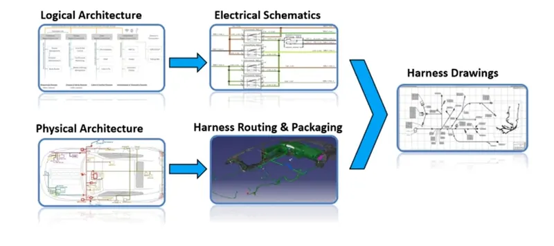
It runs from front end to rear end of the vehicle. It involves physical and logical architecture schematic development, power distribution, wiring harness design, wiring harness component design of given electrical system. It ensures the physical location of all electrical components placed in the vehicle. It provides the logical connectivity between electrical components. It has electrical controller unit for different sections like Airbag ECU, ABS ECU, Engine (ECU).
E & E Architecture
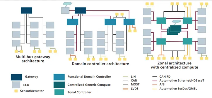
It is the high-level logical connectivity diagram. It represents all the systems, sub-systems and logical connections between them. It shows the Control Area Network (CAN) between different electronic components.
Logical Schematics
It is a detailed design of E&E architecture. It shows the logical connectivity between different components and controls of given systema and subsystem. It does not define any other parameter except electrical connectivity.
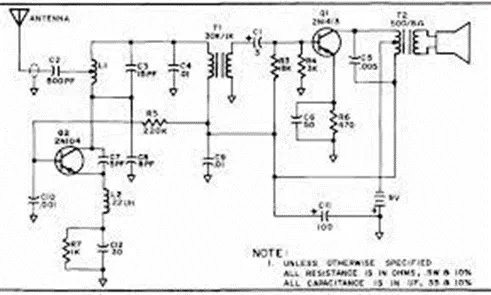
Electrical Schematics
It is a detailed design of logical schematics, pin to pin connectivity, properties, fusing distribution, grounding distribution, interconnects, wire properties (wire gauge, color, type), circuit properties (circuit number, connector designation number, control device number), specification of components, end results of electrical core design of system and primary input for harness design.
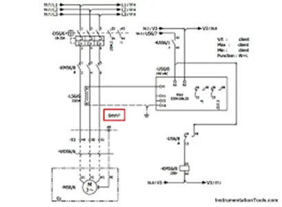
Wiring Harness Topology
Wiring harness Topology is strategy to Split the harness between different places to achieve the best manufacturability, Serviceability & cost-effective design.
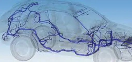
Wiring Harness Routing
A wiring harness routing structure includes a wiring harness routing member configured to be attached to a vehicle body and a protector that accommodates and holds a wiring harness.
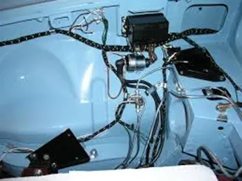
Wiring Harness Packaging
Fixing/mounting strategy of wiring harness routing to ensure the safe, reliable and durability of wiring harness by applying set of design rules and industry best practices.
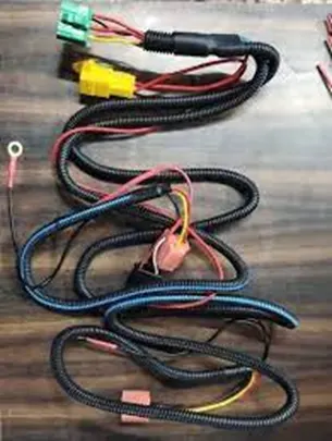
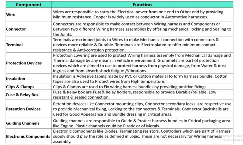
Wiring Harness Electrical Components
Typical Design Flow of EDS System
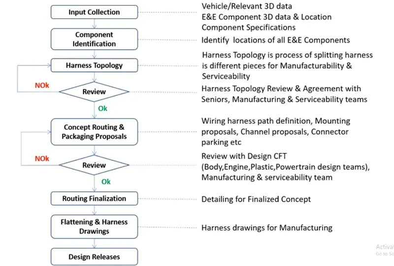
Wiring Harness Design Process
Steps Followed in Defining Part Electrically
- To define the Geometry Parameters – Points & Co-ordinate system (Axis)
- To define part as Connector
- To define Bundle Connection Point – This point defines where the harness bundle segment point will end when routed to electrical connector.
- To define Connector Connection Point – This point is used for the connection of one connector to another connector.
- To define Cavity Connection Point – This point is used to define the connection of a connector to a connector clip. This only applies to connectors which have the mounting feature for a connector clip.
CONNECTOR 1
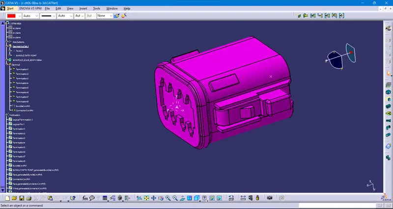
CONNECTOR 2
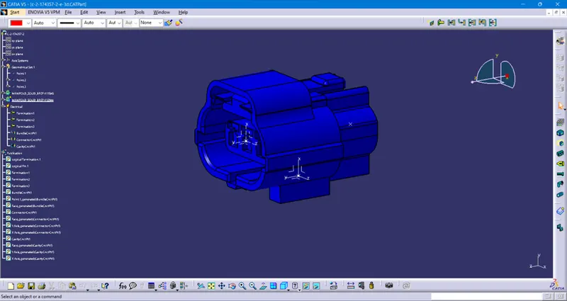
MOUNTING CLIP
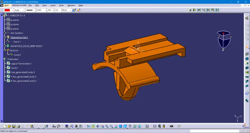
ASSEMBLY OF CONNECTOR & MOUNTING CLIP