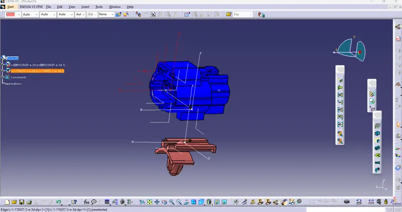
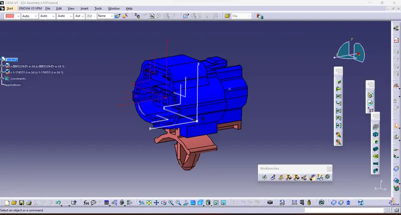
Wiring harness design in CATIA V5 - 3D modeling Week 2 Challenge
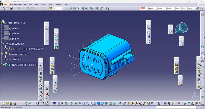
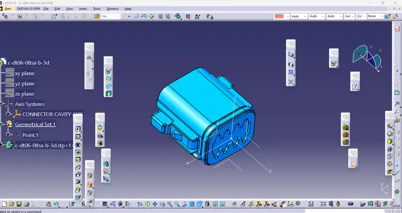
1. Deutsch DT06 – 08SA
Step 1 : Creating a connector connection point and axis on the connector cavity side and named as connector cavity axis.
Yaxis- Pointed towards front face of connector
Z axis- Pointed across connector from left to right.
X axis- Pointed towards locking clip sections
Step 2 : Creating Bundle connection point:
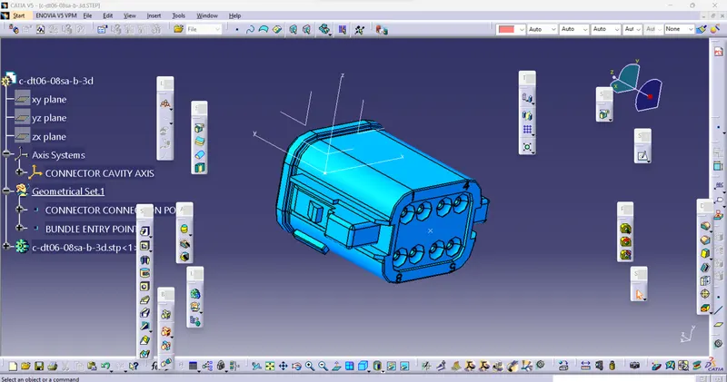
Step 3 : Define connector - This is now electricaaly defined.
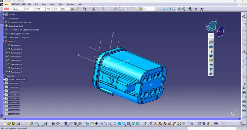
Step-4 Define Bundle connection point:
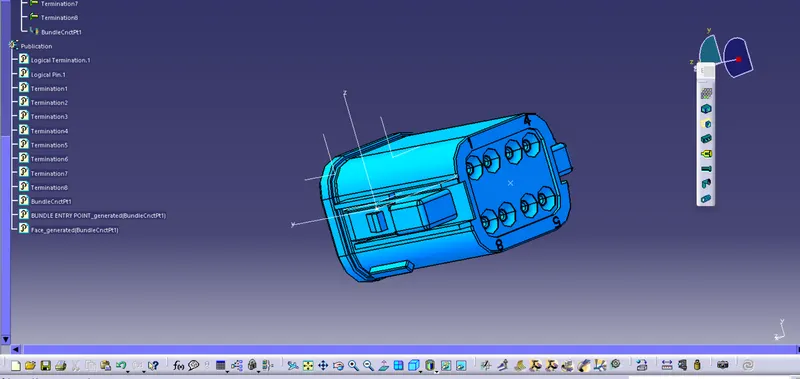
Step-5 Define Connector connection point:
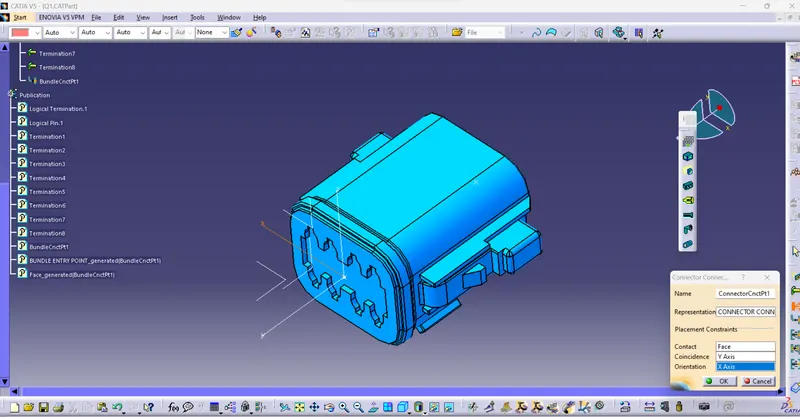
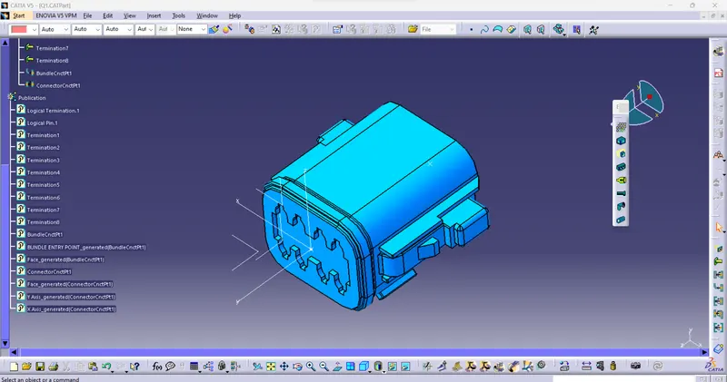
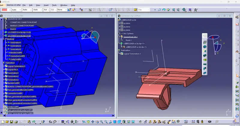
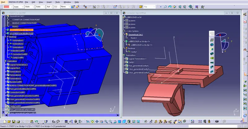
2. Tyco 174357-2
Step 1 : Creating a connector connection point and axis on the connector cavity side and named as connector cavity axis.
Yaxis- Pointed towards front face of connector
Z axis- Pointed across connector from left to right.
X axis- Pointed towards locking clip sections.
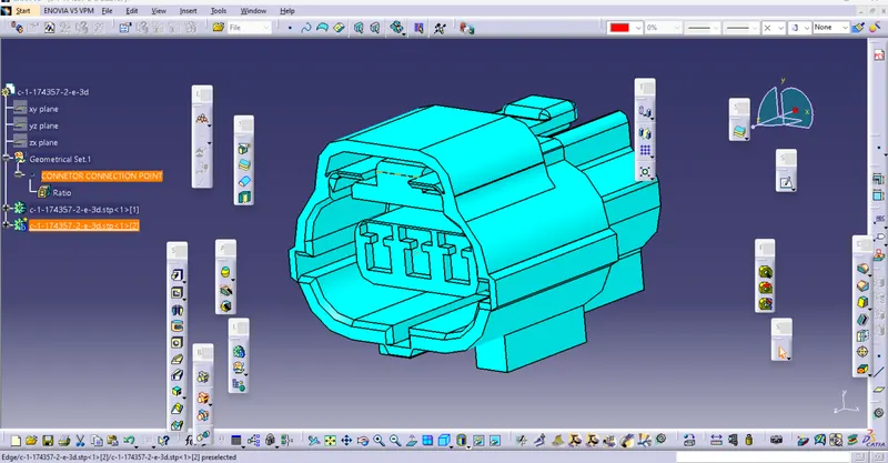
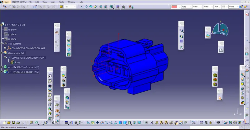
Step 2 : Creating Bundle connection point:
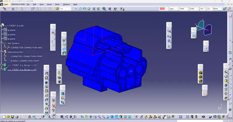
Step 3 : Define connector - This is now electricaaly defined.
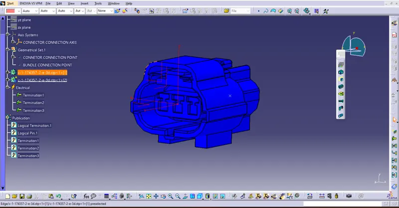
Step-4 Define Bundle connection point:
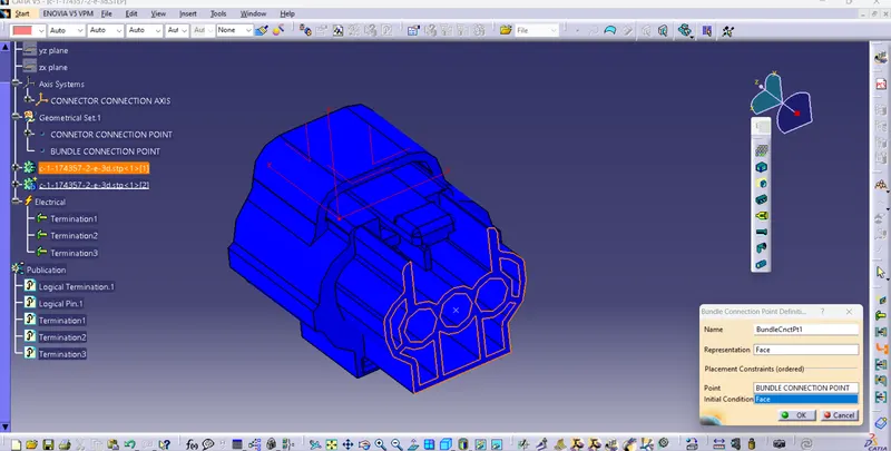
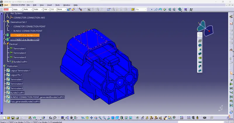
Step-5 Define Connector connection point:
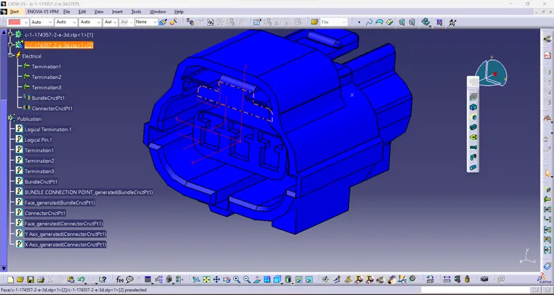
Step6- Create connective connection point and axis and thus define it.
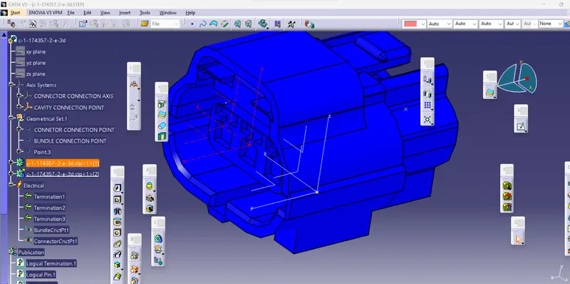
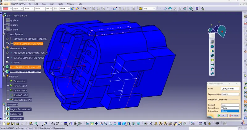
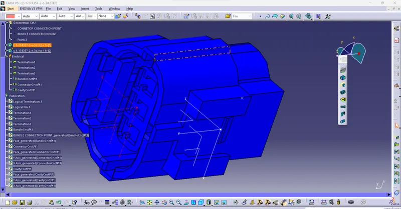
Step7- Connector clip axis setting and Define clip as mounting component and finally define Cavity:
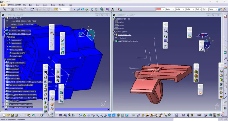
ASSEMBLY: