Wiring harness design in CATIA V5 - 3D modeling Week 2 Challenge
Wiring harness design in CATIA V5 - 3D modeling Week 2 Challenge
Aim : To download following connectors & Connector clip cad data from given link & define it as Electrical Connector using Electrical Part design Workbench. Define all the necessary properties to Connectors & Clip.
Given input CAD model from given input links from challenge.
INPUTS:
1.DEUTSCH - DT06-08SA
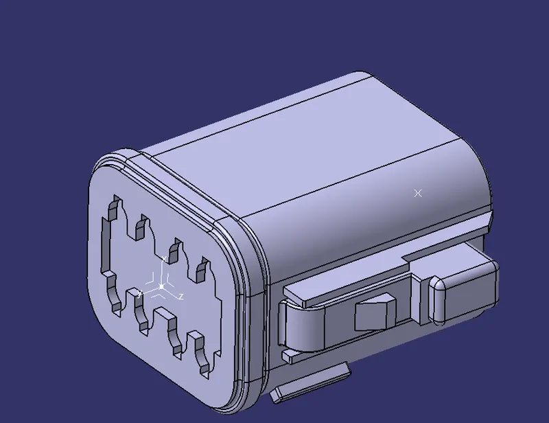
Housing for female terminals, wire to wire, 8 position,359 in [9.12 mm] centerline, sealable, gray, wire & cable, power & signals these are components specification of given connector.
2.Tyco 174357-2
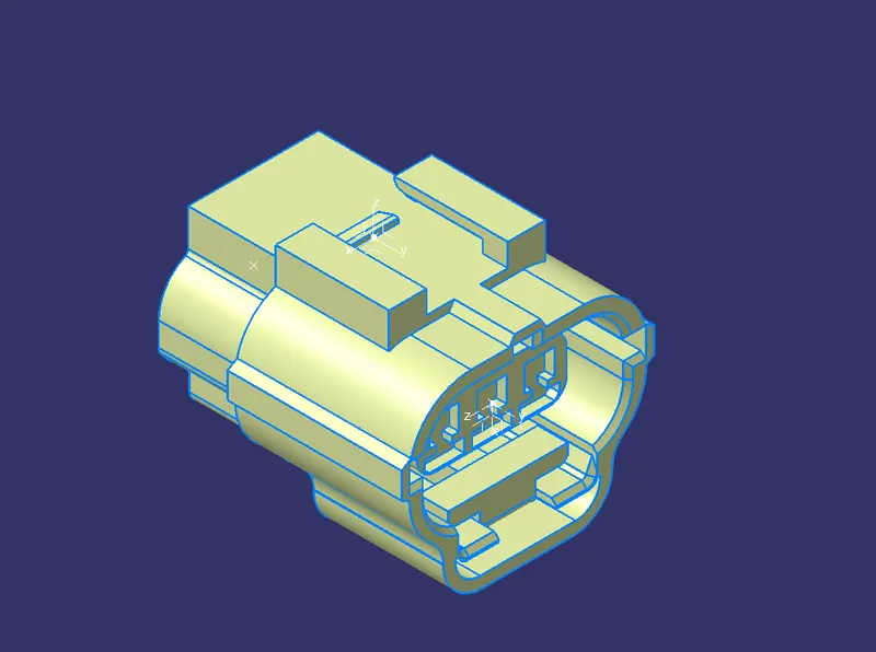
3.Tyco 85229-1
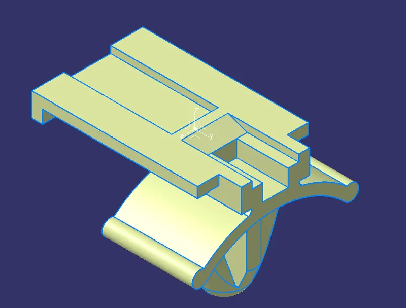
Other Automotive connector Accessories, Mounting clip, PA, black, -40 -120 °C [-40 -248 °F ], Econoseal these are components specification of given mounting clip.
Defining different properties of given connectors and mounting clip and properties definitions and uses:
Following parameters are required to defined for any connctor.
1.Download the given connector 3D part from links.
2.Geometry properties: points and Axis system
Example: Deutsch/Tyco-DT06-08SA-CE13
Select the start > mechanical design > part design in the CATIA V5 the connector axis system should be on the front face of the connector attached to a point on 0,0,0 coordinates. This point should be in the centre of the front face as this point will be used to connect the connector to another electrical component.
Z-Axis should be point across the connector from left to right.
Y-Axis should be pointing towards the face of the connector (same direction as the harness to the connector).
X_Axis should be pointing in the dorection towards the locking mechanism of the clip.
we can use the our own axis but it should be consisting for the mating connectors.
3.Connector connection point: This point is used for the connection of one connector to another connector.
4.Harness bundle entry point: This point defines where the harness bundle segment point will end when routed to the electrical connector.
5.Cavity coonection point: This point is used to define the connection of a connector to coonector clip. This only applies to the connectors which have the routing for the connector clip.
Defining necessary properties to Connectors & Clip.
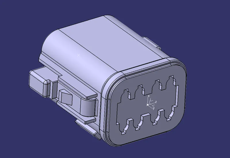
1.DEUTSCH - DT06-08SA
- Defining geometrical properties (points and axis system)
Bundle entry side center point -
Selecting two random points diagonally to get a center point, under point type between.
Mating side center point -
Selecting two random points diagonally to get a center point, under point type between.
Mating side axis system -
Creating an axis system concerning the center point as the origin of the axis. The Y axis is directed at the mating direction, the X axis is directed towards the locking side and the Z axis is directed upwards.
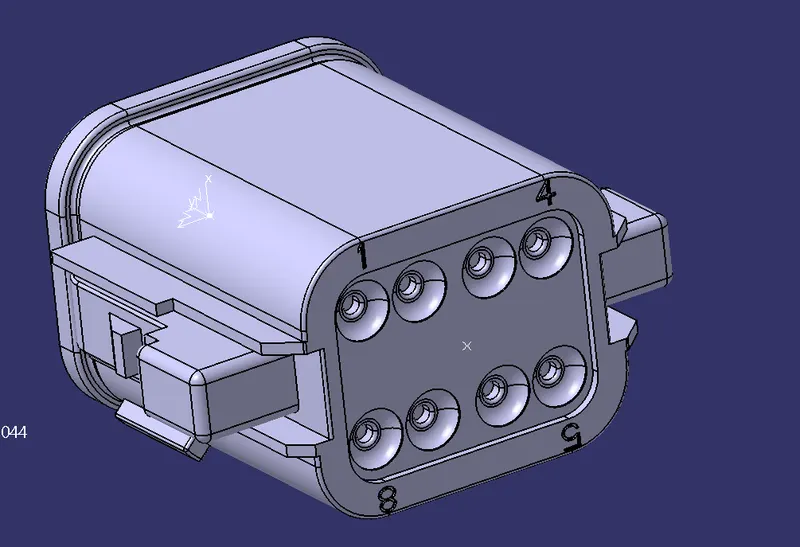
ii. Electrical Part Design Workbench
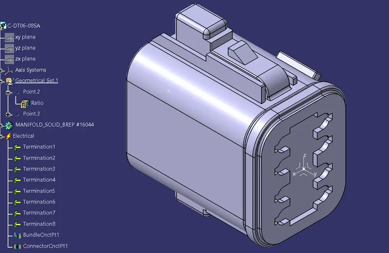
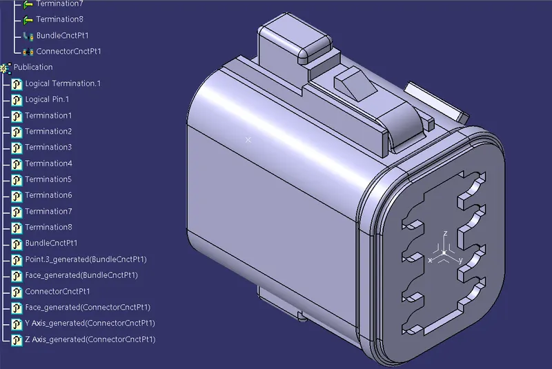
- Define part as a connector
Defining part as an electrical connector under Electrical Part Design Workbench. Selecting the number terminations 8.
Define bundle connection point (bundle/wire entry side)
Defining bundle connection point at the bundle entry side where, representation is the face, point as the center point, and initial condition also as the face.
- Define connector connection point (mating side)
Defining connector connection point at the mating side of the connector where representation is the center point, contact is the face, coincidence is the Y axis, and, orientation is the X axis.
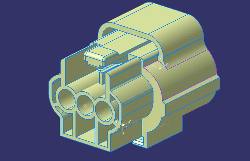
2.Tyco 174357-2
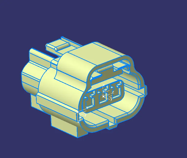
- Defining geometrical properties (points and axis system)
Bundle entry side center point -
Selecting two random points diagonally to get a center point, under point type circle/sphere/ellipse center.
Mating side center point -
Selecting two random points diagonally to get a center point, under point type between.
Mating side axis system -
Creating an axis system concerning the center point as the origin of the axis. The Y axis is directed at the mating direction, the X axis is directed upwards and the Z axis is directed to the side.
Selecting the edge of the cavity connection part to get a center point, under point type on the curve.
Creating an axis system concerning the center point as the origin of the axis. The Y axis is directed at the connection direction, the X axis is directed upwards and the Z axis is directed to the side.
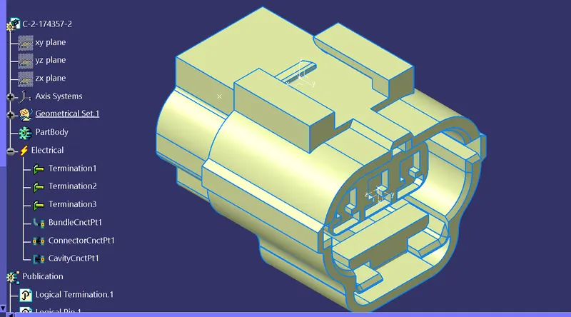
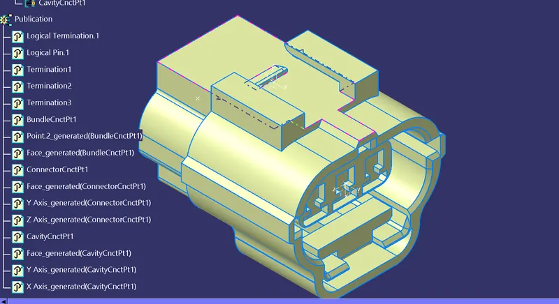
ii. Electrical Part Design Workbench
- Define part as a connector
Defining part as an electrical connector under Electrical Part Design Workbench. Selecting the number terminations 3.
- Define bundle connection point (bundle/wire entry side)
Defining bundle connection point at the bundle entry side where, representation is the face, point as the center point, and initial condition also as the face.
- Define connector connection point (mating side)
Defining connector connection point at the mating side of the connector where representation is the center point, contact is the face, coincidence is the Y axis, and, orientation is the X axis.
- Define cavity connection point (optional, if connector needs mounting clip)
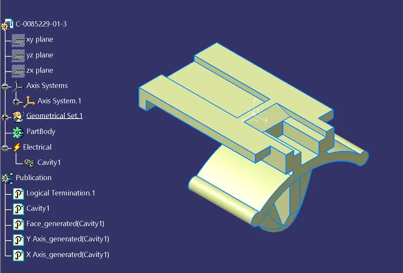
A cavity connection is defined as the connecting part for a connector clip where representation is the center point of the cavity connection, contact is the connection face, coincidence is the Y axis and, orientation is the X axis.
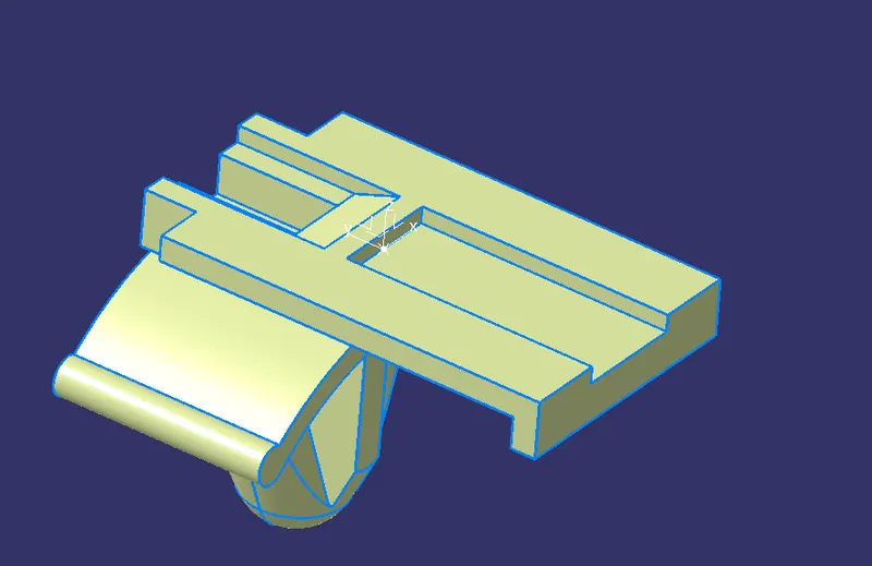
3.Tyco 85229-1
i. Mechanical Part Design Workbench
- Defining geometrical properties (points and axis system)
Mounting clip center point -
Selecting the edge of the connecting part to get a center point, under point type curve.
Mounting clip axis system -
Creating an axis system for the cavity, the origin is the center point, the Y axis is directed towards the insertion, the X axis is directed upwards and, the Z axis is directed to the side. The axis direction should follow the connector's cavity connection axis direction for proper mounting.
ii. Electrical Part Design Workbench
- Define part as a Mounting Equipment
The clip is defined as electrical mounting equipment.
- Connect Electrical Devices
The connector and connector clip are connected under the electrical assembly design workbench using connected electrical devices.
Two connectors are not matinf each other properly for faces and locking slots are different and termals are differnt design.
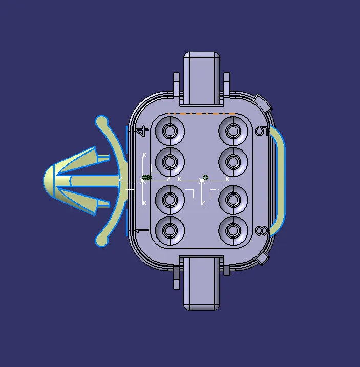
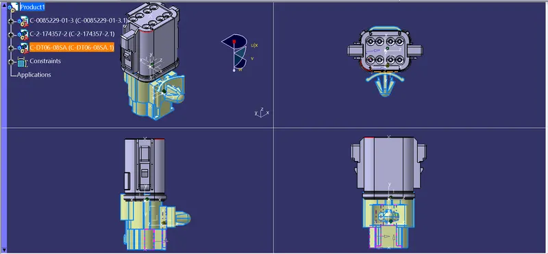
Conclusion: Hense finally defined it as Electrical Connectors using Electrical Part design Workbench. Defined all the necessary properties to Connectors & Clip.