Wiring harness design in CATIA V5 - 3D modeling Week 2 Challenge
WIRING HARNESS CHALLENGE WEEK 2 - REPORT
OBJECTIVE :
Download following connectors & Connector clip cad data from given link & define it as Electrical Connector using Electrical Part design Workbench. Define all the necessary properties to Connectors & Clip.
- Deutsch DT06-08SA (https://www.te.com/usa-en/product-DT06-08SA.html)
- Tyco 174357-2 (https://www.te.com/usa-en/product-2-174357-2.html?source=header-match)
- Tyco 85229-1 (https://www.te.com/usa-en/product-85229-1.html?q=85229&source=header)
SOFTWARE USED :
- CATIA V5
WIRING HARNESS ASSEMBLY STRUCTURE - CONNECTOR DEFINITION :
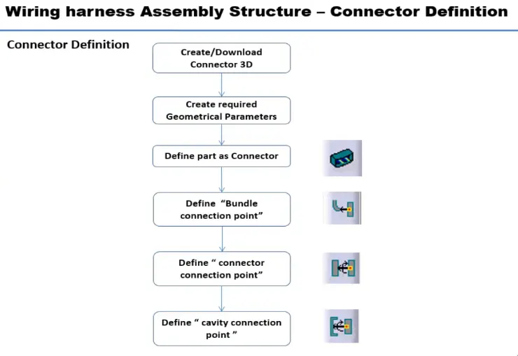
CONNECTOR DEFINITION :
Following parameters are required to define any connector -
- Geometry Parameters - Points & Co-ordinate system (Axis)
- Connector connection points - This point is used for the connection of one connector to another connector.
- Harness bundle entry point - This point defines where the harness bundle segment point will end when routed to the electrical connector.
- Cavity connection point (Optional) - This point is used to define the connection of a connector to a connector clip. This only applies to connectors which have the mounting feature for a connector clip.
CONNECTOR DEFINITIONS IN CATIA V5 :
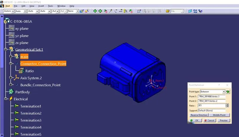
- Deutsch DT06-08SA :
Connector Mating Side:
- Create midpoint on the contact face of mating side of Connector in Mechanical Part Design
- Create an axis system on this point with direction defined as shown in below image.
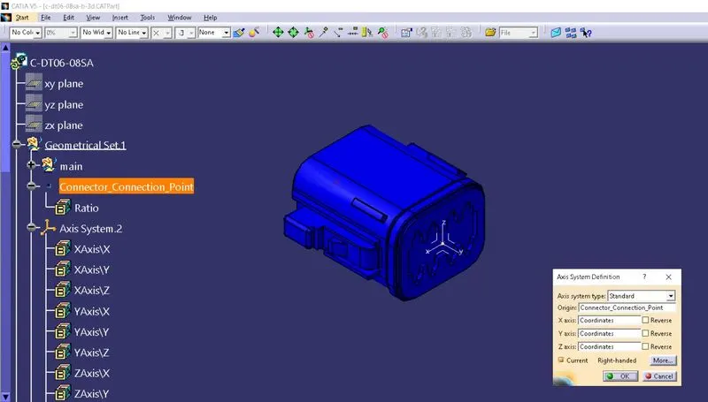
Wire Bundle Entry Side:
- Create midpoint on the contact face of wire bundle entry side as per the image.
- Define the part as electric part.
Define as Electric Part:
- Choose ‘Electric Part Design’ workbench.
- Define the part as CONNECTOR in this workbench & give name of part and number of terminals as 8 according to image.
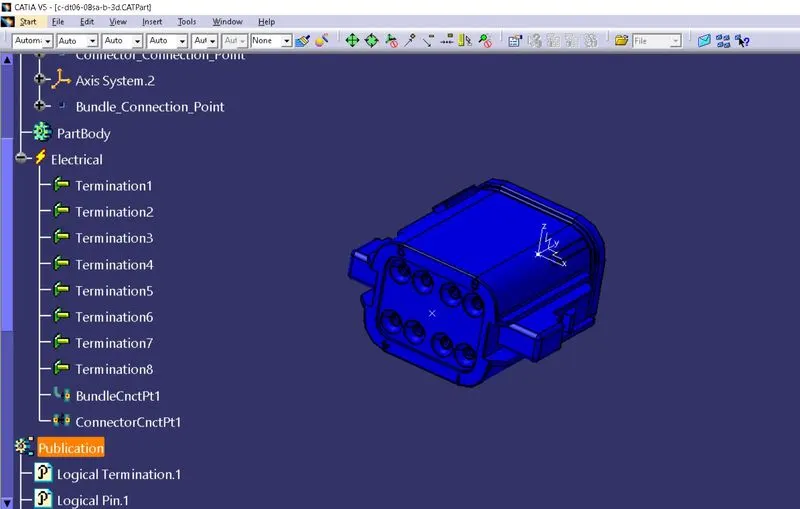
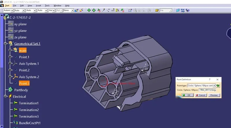
- Define Bundle Connection Point by selecting face and point.
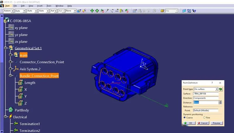
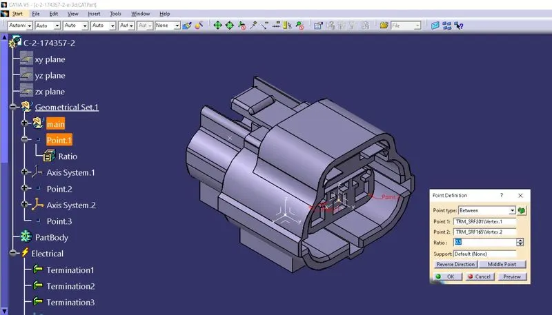
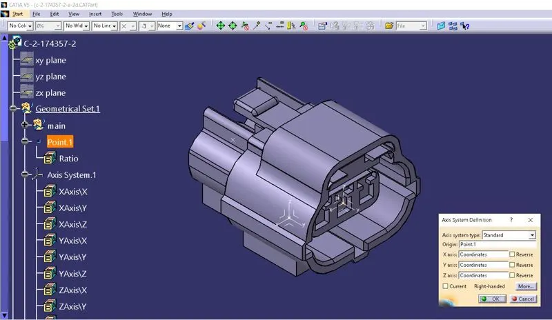
- Define Connector Connection Point by selecting face, point as well as Y & X axis as shown in figure.
- Tyco 174357-2 :
Bundle Connection Point :
Connector Connection Point :
Connector Point Axis System :
TERMINALS :
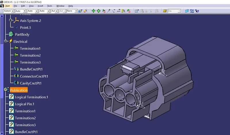
- Follow same procedure as mentioned above to define this connector.
- Here one new thing to define which is Cavity Connection Point.
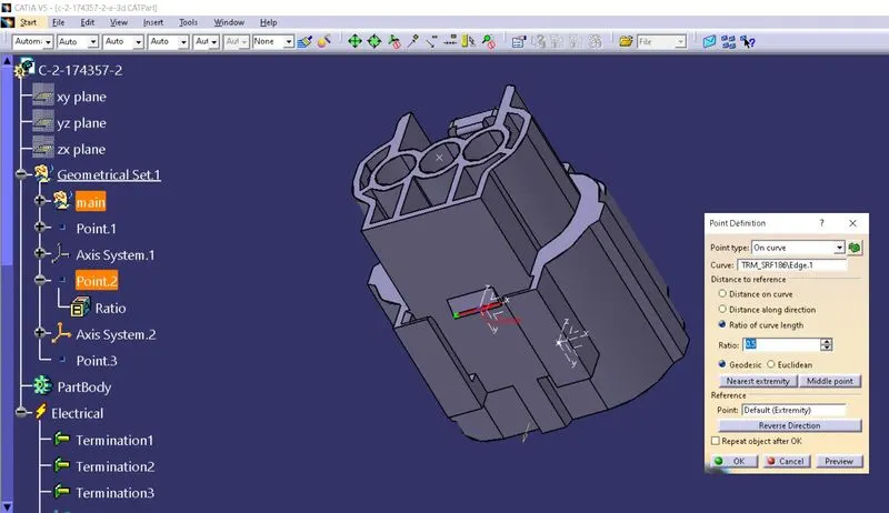
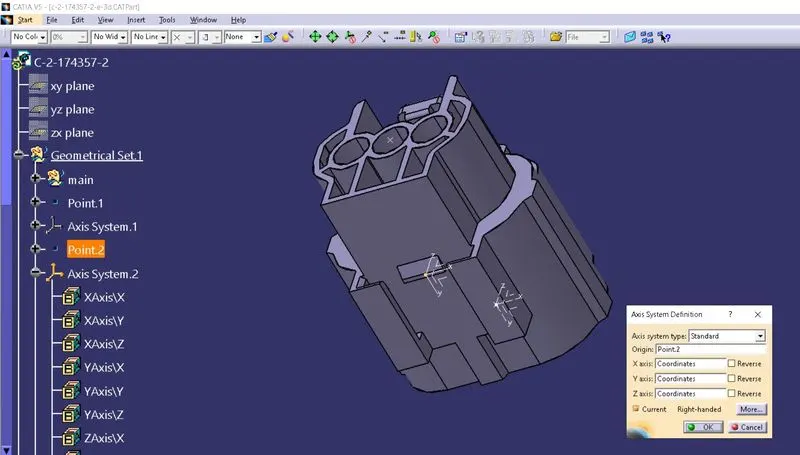
- Create a point on mating face and insert a new axis system.
- Define Cavity Connection Point by selecting the given point, face and Y & X axis as shown in figure.
- Tyco 85229-1 :
Cavity :
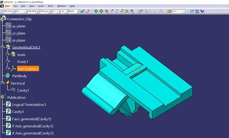
- Follow same procedure as mentioned above to define this connector.
- Here one new thing to define which is Cavity.
- Create a point on mating face and insert a new axis system by comparing it with the mating Connector.
- Define Cavity Connection Point by selecting the given point, face and Y & X axis as shown in figure.
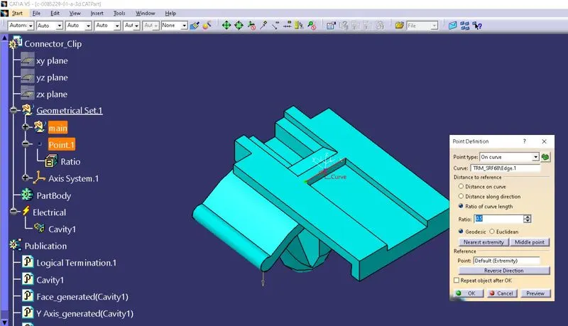
Cavity Axis System :
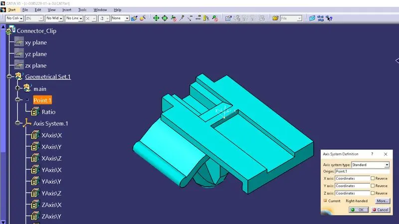
CREATION OF CONNECTOR & CLIP ASSEMBLY :
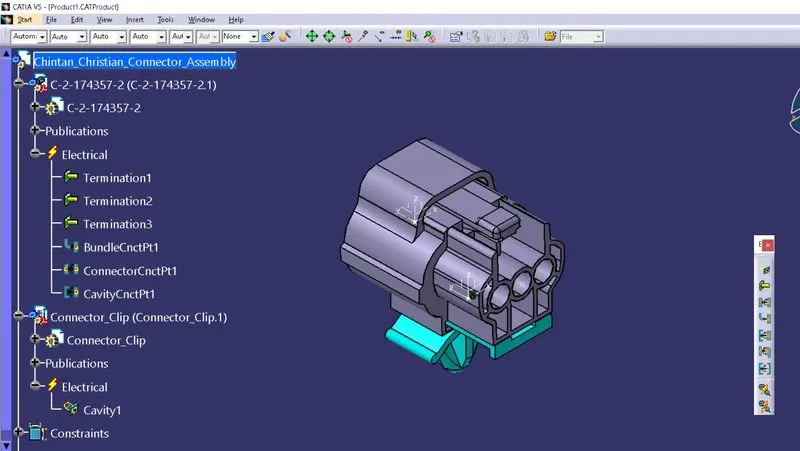
- Import Connector and Connector clip to a new assembly file. Arrange both parts as per required orientation.
- Go to Electrical Assembly Design
- Use Connect Electric Connection.
- First choose Clip and then Connector.
- Both will automatically connected as per given constraints.
CONCLUSION :
I have learned about how to define connectors and clips as electrical parts as well as I have also learned about how to define assembly as Electrical and how apply to Electrical Connections with different parts from this presented challenge.