Wiring harness design in CATIA V5 - 3D modeling Week 2 Challenge
INTRODUCTION TO WIRING HARNESS DESIGN USING CATIA V5
OBJECTIVE: The main motive or objectives of this challenge are given below
• To understand the basic concepts of wiring harness design workbenches.
• To define all the necessary properties of Connectors & clips.
• To prepare a detailed report explaining all the things by attaching images wherever and whenever required.
WIRING HARNESS :
A wire harness, often referred to as a cable harness or wiring assembly, is a systematic and integrated arrangement of cables within an insulated material. The purpose of the assembly is to transmit a signal or electrical power. Cables are bound together with straps, cable ties, cable lacing, sleeves, electrical tape, conduit, or a combination thereof. The wire harness simplifies the connection to larger components by integrating the wiring into a single unit for “drop-in” installation.
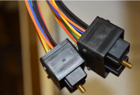
CONNECTOR :
Connectors are the electro-mechanical devices used to form a continuous electronic signal to connect wire harnesses to a power source or circuit. On a basic level, connectors consist of male-ended plugs and female-ended jacks that can be joined together to relay an electronic signal.
In general, these are plastic molded housing with locking and retention features.
Connectors attach to or pass the wires through a component. They are water and heat-resistant. A hard outer shell with a locking clip holds two halves of a connector together. The pins and sockets are crimped to the wire both at the insulation and the bare wire. They are made so that they fit together perfectly, but can also be easily disconnected when needed. A rubber seal encloses all the wires and keeps the wires protected from moisture and other abrasive conditions.
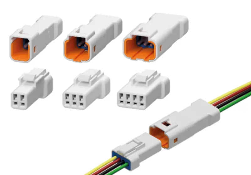
CONNECTOR 1 :
Now let us observe the given part of the connector,
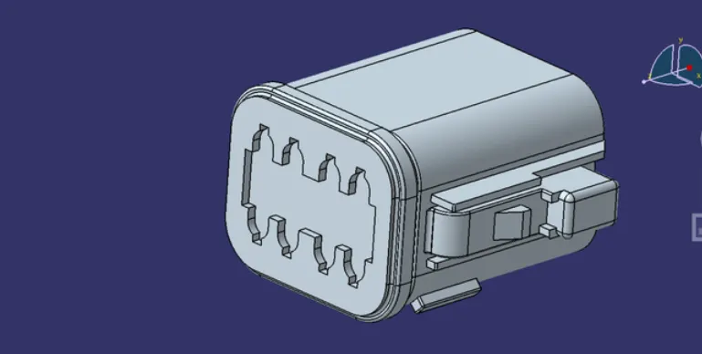
Create a connector connecting point on the front side of the connector by using the point command in the part workbench and make sure the point is at the center.
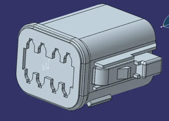
The next step in this process is to create an axis system and rename the axis system as connector cavity axis system. There is no specific rule for the direction of the axes, the axis which i have created is shown in below figure,
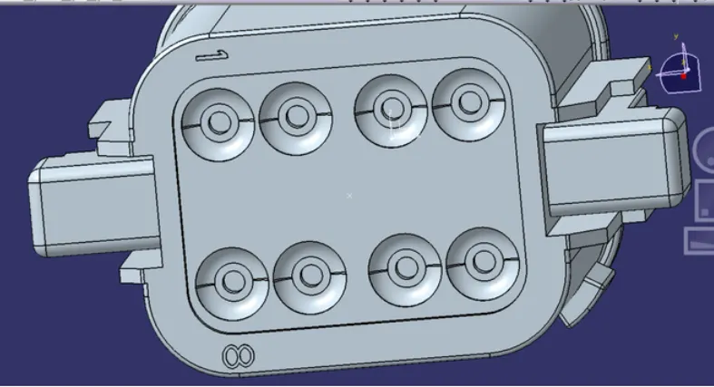
Now create a centre point on the rear side of the connector and rename that as bundle entry point.
• Go to electrical part design workbench and define the connector by selecting the body and by giving proper number of terminals.
• Use define bundle connection point and select the required profies
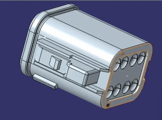
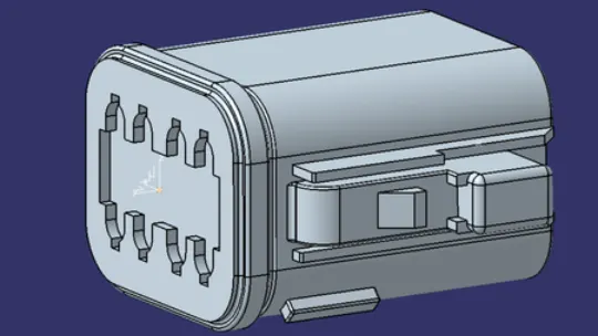
• By using define connector connecting point command, select the body first and then made selection as given in the below image.
CONNECTOR 2 :
The given connector is as shown in the below image,
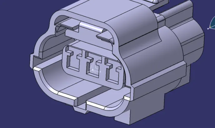
Now here also repeat the same procedure what we have done for the connector 1 and images related to the connector 2 are attached below,
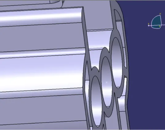
In this connector we have a slot for a clip, so have to define the attaching strategy of the clip to the connector, for that create a point on the bottom side of the connector where the clip is going to attach as shown in below figure,
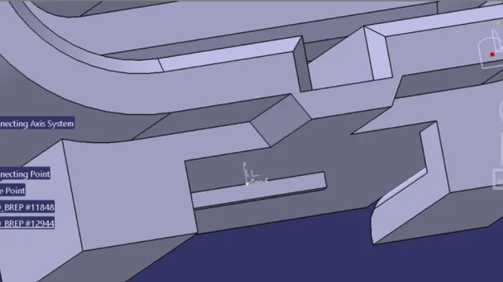
Now create an axis system similar to the axis system which we have used previously by taking the point as an origin.
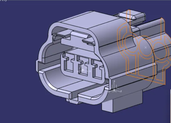
• Go to electrical part design workbench and define the connector by selecting the body and by giving a proper number of terminals.
• Use defines bundle connection point and selects the required profiles.
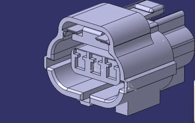
• By using define connector connecting point command, select the body first and then made a selection as given in the below image.
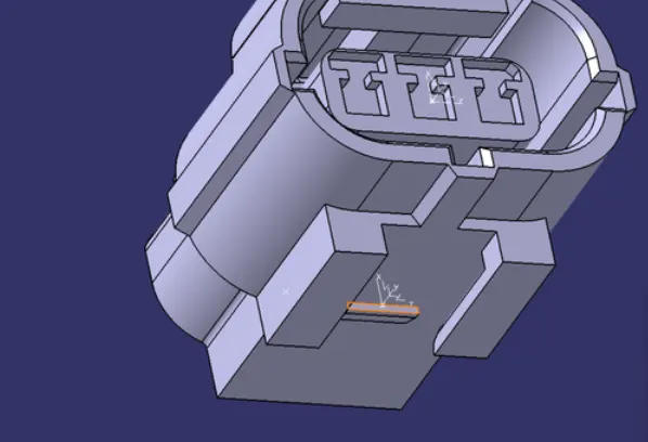
Here by using define cavity connection point select the things as shown in the below figure related to the slot.
CONNECTING CLIP:
Let us see how the connecting clip looks which is shown in below figure,
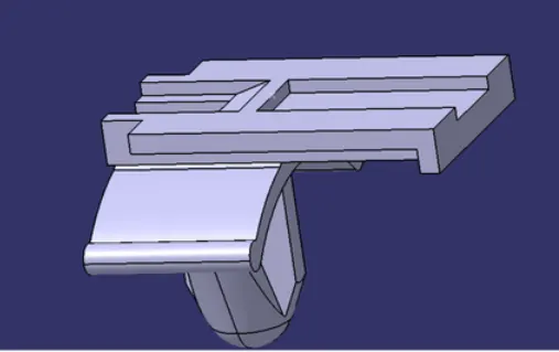
Create an axis system by taking the Centre on the curve as an origin point and ensuring the axis is the same as the axis we created on the mating connector.
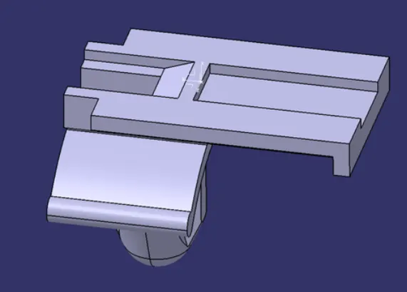
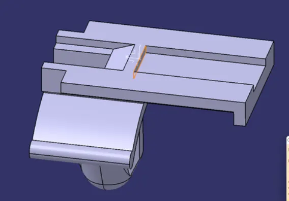
Define that a cavity in the electrical part design workbench and select the thins in accordance.
ASSEMBLY OF CONNECTOR AND CLIP:
Now we will see how to assemble electrical parts in the electrical assembly design workbench. Here we are using the electrical assembly design workbench instead of the mechanical assembly workbench because it will ease our work to a single step instead of using various constraints. In the electrical assembly design workbench, the CATIA will automatically apply suitable constraints to the electrical parts automatically.
After loading the parts to the workbench make them oriented properly after that by using connect electrical devices command select one component and the CATIA software will automatically detect the possible mating pat and select that part.
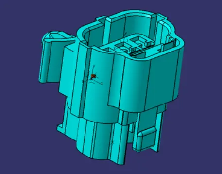
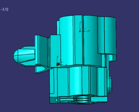
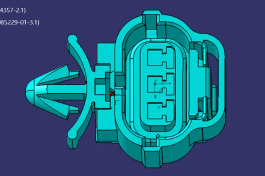
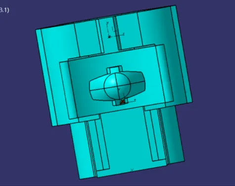
The views of assembled parts are shown below pictures,
ISOMETRIC VIEW
FRONT VIEW
TOP VIEW
SIDE VIEW
CONCLUSION
hence the objectives of the challenge have been accomplished and the components are added to the catalog which has been created earlier.