Wiring harness design in CATIA V5 - 3D modeling Week 2 Challenge
Aim :-
Download following connectors & Connector clip cad data from given link & define it as Electrical Connector using Electrical Part design Workbench. Define all the necessary properties to Connectors & Clip.
- Deutsch DT06 – 08SA ( https://www.te.com/usa-en/product-DT06-08SA.html)
- Tyco 174357-2 (https://www.te.com/usa-en/product-2-174357-2.html?source=header-match)
- Tyco 85229-1 – (https://www.te.com/usa-en/product-85229-1.html?q=85229&source=header)
*Terminology & Definations*
- Electrical Distribution & system(EDS) :- Electrical distributions and system(EDS) basically deals with phisical and logical architecture,schimatic develoupment,power disribution,wiring harness design,wiring harness component design of even electrical system.
- E&E Architecture :- It's high level logical connectivity digram represent the number of sub-system &logical connectivity between them. It is also extended show the CAN network between defferent electronic controllers.
- Logical schematic :- Logical schematic is detailed design of E&E architecture which extended to show the logical connectivity between defferent component & controls of given system,sub-system.
- Electrical schematic :- Electrical schematic is detailed design of logical schematic which discribe the pin to pin connectivity, properties,fusing distribution,graounding distribution,interconnects,wire properties,circute properties, specifiction of components,etc. This is the end result of core design of system and used as an primary input for harness design.
- Wiring Harness Topology :- It is a strategy of divided or split the harness between defferent pieces of achieve the best manufacturability,servisability & cost effective design.
- Wiring Harness Routing :- It is deals with desired path of wiring harness of given vehicle environment by applying set of desing rules and industry best practices.
- Wiring Harness Packaging :- It is deals with fixing/mounting strategy of wiring harness routing of ensure the safe, reliable & durability of wiring Harness by applying set of desing rules and industry best practices.
1)
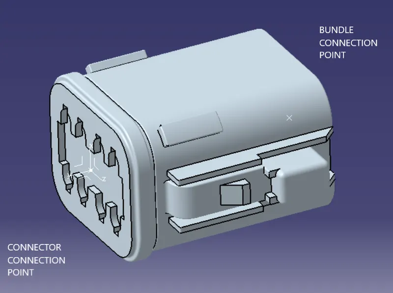
- THE CONNECTOR IS FIRST UPLOADED IN THE PART DESIGN WORKBENCH
- WE DEFINE THE POINTS FOR CONNECTOR CONNECTION AND BUNDLE CONNECTION.
- THE AXIS SYSTEMS ARE PLACED ON THE CONNECTOR CONNECTION AND CAVITY CONNECTION POINTS
- THE ORIENTATION OF THE AXIS SYSTEM IS NOT SPECIFIC, WE JUST NEED TO FOLLOW A SIMILAR ORIENTATION FOR ALL THE PARTS.
- HERE THE Y-AXIS IS IN THE DIRECTION OF THE CONNECTION, Z-AXIS ALONG WITH THE CLIP MOUNTING AND X-AXIS ALONG BOTTOM TO TOP.
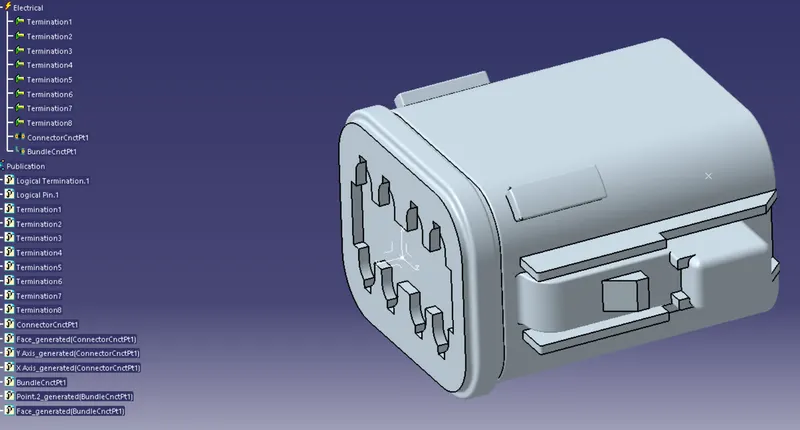
- NOW WE DEFINE THIS PART AS AN ELECTRICAL ELEMENT/CONNECTOR, WITH THE NUMBER OF TERMINALS.
- CONNECTOR CONNECTION AND BUNDLE CONNECTION IS DEFINED IN THE ELECTRICAL PART DESIGN WORKBENCH.
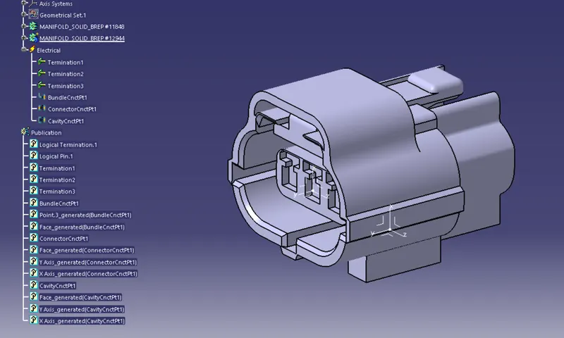
2) THE SAME PROCESS WAS FOLLOWED FOR THE SECOND CONNECTOR. HERE WE NEED TO INCLUDE THE CONNECTOR-CAVITY CONNECTION POINT. THIS IS DONE TO FIX THE CLIP ON TO THE CONNECTOR.
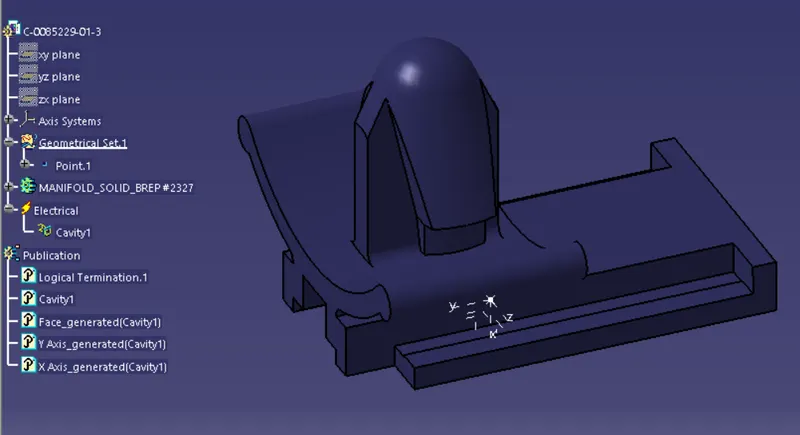
THE CLIP HAS TO BE DEFINED AS A CAVITY IN THE ELECTRICAL PART DESIGN WORKBENCH.